17 posts tagged with "RK3576"

View All Tags

OPENWRT System 5: Docker Use Case Guide

· 10 min read
Yuxuan
100askTeam yuxuan.

Docker is an open-source containerization platform that encapsulates applications and their runtime environments through "containers", enabling applications to run quickly and stably across different systems. Containers are lightweight, start fast, and consume few resources, making them suitable for microservice deployment and continuous integration/delivery. Docker also provides image management, version control, and environment consistency, keeping development, testing, and production environments unified, greatly improving deployment efficiency and portability. Docker allows developers to package their applications and dependencies into a lightweight, portable container, then publish to any popular Linux machine, and can also implement virtualization.

Hardware environment: OpenWrt runs on a high-performance ARM SBC (such as the Dshanpi-A1 used in this article), with common home devices like an optical modem + switch/AC/AP.
Goal: Use Docker on this SBC to run home theater + downloader + network drive + ad filtering + simple monitoring, one machine for multiple uses.

Home Network

  • Optical modem in bridge mode, delegating PPPoE dialing to OpenWrt on the ARM SBC
  • ARM SBC serves both as the main router and as a "lightweight NAS + home theater server"
  • TV box, mobile phone, and computer are all connected to the LAN (wired or wireless), uniformly accessing services on the SBC

Machine Configuration

  • Device: ARM 64-bit architecture SBC, 8G memory version
  • System: OpenWrt (self-compiled/integrated firmware both work, the key is to have Docker)
  • Disk:
    • System disk (eMMC/TF) for OpenWrt
    • External SSD/HDD/large USB drive as data disk, mounted to /mnt/data

Docker Environment & Directory Planning

First confirm the environment and directory planning, which makes maintenance easier later. This step is critical.

Install Docker / Docker Compose

If your firmware already has Docker packaged, you can skip the installation. It is recommended to install luci-app-dockerman, which is a dedicated Docker Web management interface plugin for OpenWrt:

opkg install luci-lib-docker dockerd luci-lib-jsonc docker ttyd --force-depends
opkg install luci-app-dockerman
  • dockerd: Docker daemon
  • docker: Command-line client
  • luci-lib-docker / luci-lib-jsonc: Dockerman dependencies
  • ttyd: For Web terminal and container console
  • luci-app-dockerman: Web management interface plugin

Start and set to auto-start on boot:

/etc/init.d/dockerd start
/etc/init.d/dockerd enable

Then access the LuCI backend, and the menu will have an additional: Services / Docker or Services / Dockerman.

You can also confirm the environment works via command line, as shown below:

root@LEDE:~# docker version
Client:
Version: 28.0.4
API version: 1.48
Go version: go1.25.4
Git commit: b8034c0
Built: Sun Sep 7 14:53:18 2025
OS/Arch: linux/arm64
Context: default

Server:
Engine:
Version: 28.0.4
API version: 1.48 (minimum version 1.24)
Go version: go1.25.4
Git commit: 6430e49
Built: Sun Sep 7 14:53:18 2025
OS/Arch: linux/arm64
Experimental: false
containerd:
Version: 1.7.27
GitCommit:
runc:
Version: 1.2.6
GitCommit:
docker-init:
Version: 0.19.0
GitCommit: de40ad0
root@LEDE:~# docker ps
CONTAINER ID IMAGE COMMAND CREATED STATUS PORTS NAMES
root@LEDE:~#

Seeing the version information & empty container list means it's OK.

docker-compose is also recommended to install for managing multiple services together later (taking ARM64 as an example):

wget https://github.com/docker/compose/releases/download/v2.27.0/docker-compose-linux-aarch64 -O /usr/local/bin/docker-compose
chmod +x /usr/local/bin/docker-compose
docker-compose version

Data Disk Mount & Directory Planning

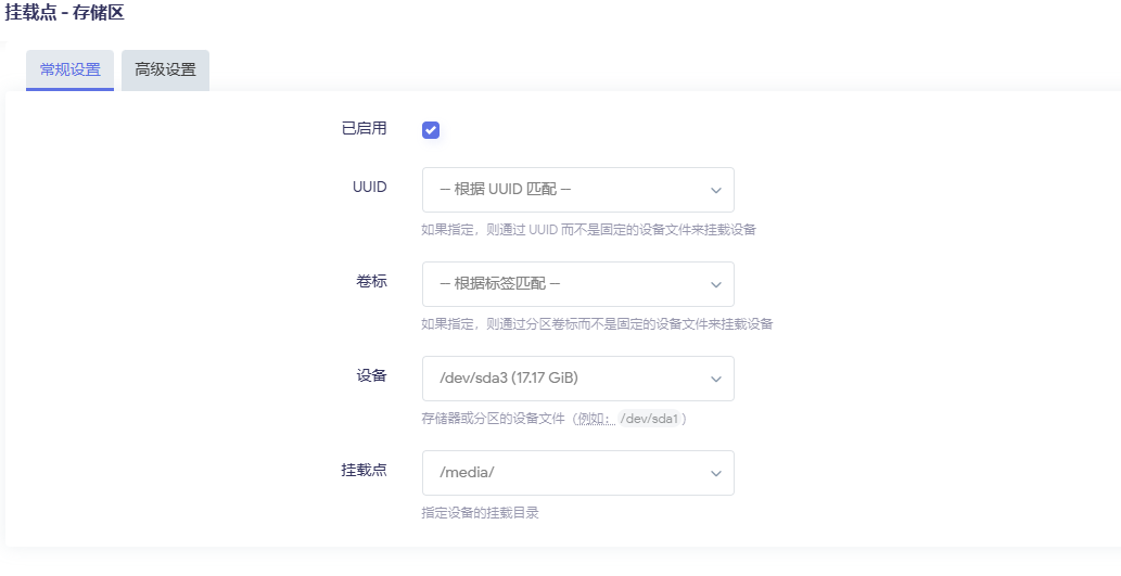
First, create a new partition in the remaining eMMC space, format it as ext4, then mount it on the interface as the docker data partition. Of course, you can also use other external storage devices, such as a TF card as the docker data partition, just add the corresponding mount directory configuration. An example is as follows:
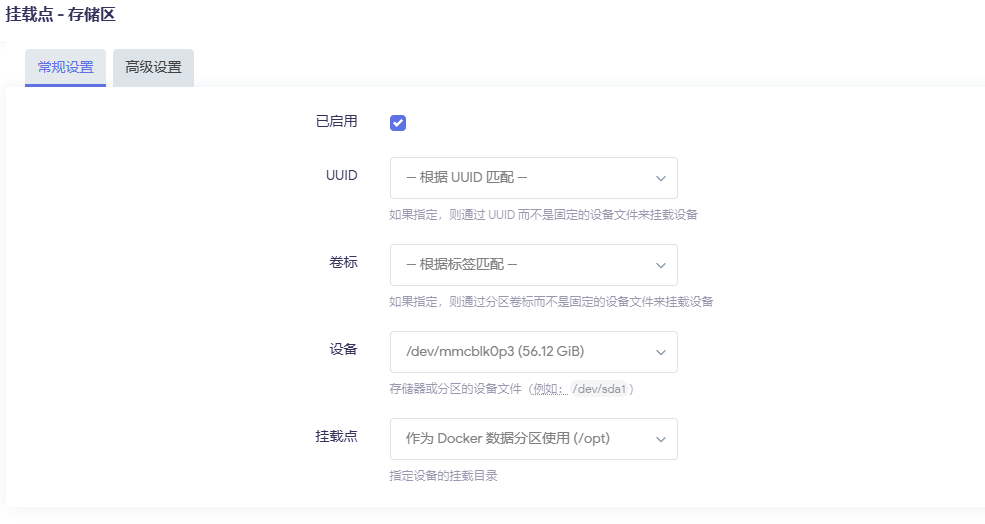
With the data disk rooted at /opt/data, you can plan it like this:

/opt/docker      # Docker root directory (images, container layers, etc.)
/opt/data
├─ media # Media files (movies, TV series, music)
│ ├─ movies
│ └─ tv
├─ downloads # BT/PT download directory
└─ configs # Configuration files for each container
├─ jellyfin
├─ qbittorrent
└─ ...

Then create the directories:

mkdir -p /opt/data/{configs,downloads,media}
mkdir -p /opt/data/configs/{jellyfin,emby,transmission,qbittorrent,aria2,adguard,nextcloud}
mkdir -p /opt/data/media/{movies,tv,anime,music}
mkdir -p /opt/data/downloads/{bt,aria2,tmp}

Later, all containers should try to be mounted under /opt/data to avoid filling up the system disk.

Benefits of doing this:

  • If a container breaks, just delete and rebuild it, data is unaffected
  • When changing devices, just connect this disk over and modify the path to continue using it

Configure Kernel Options to Support Docker

With the default compiled kernel, docker will have warning messages when running, prompting that certain feature support is missing, as shown below:
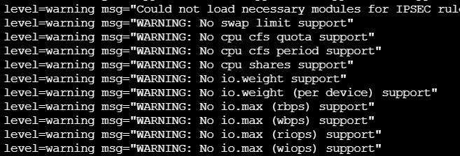
These WARNINGs indicate that your kernel has not enabled the cgroup v1/v2 resource limit functions, causing Docker to be unable to limit CPU, IO, memory swap, etc. for containers. We need to enable the following configurations in our system:

# Open the kernel configuration page
make kernel_menuconfig

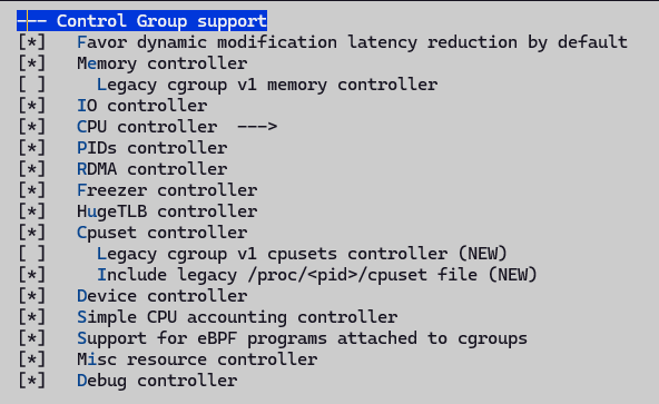
According to the configuration below, enable CGroup and Namespace support:

Recompile, then upgrade. After booting, confirm there are no corresponding error messages. For more configuration support, please check the configuration in the code repository.

Note: Some docker versions require enabling legacy cgroup v1 related control support. Keep this disabled here.

Acceleration Source Configuration

  1. When installing the docker images below, the default repository download may fail. You can configure mainland sources to accelerate downloads;
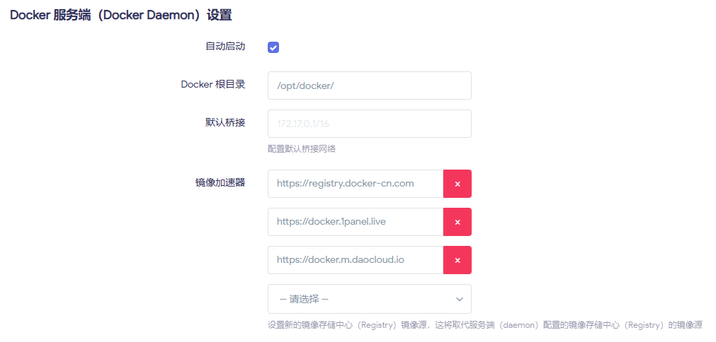
Common acceleration mirror site addresses:

{
"registry-mirrors": [
"https://docker.1panel.live",
"https://registry.docker-cn.com",
"http://hub-mirror.c.163.com",
"https://docker.m.daocloud.io"
]
}
  1. If you find that the configured acceleration source is inaccessible, it may be due to the installed openwrt proxy plugin. Modify the configuration or disable the proxy and retry;
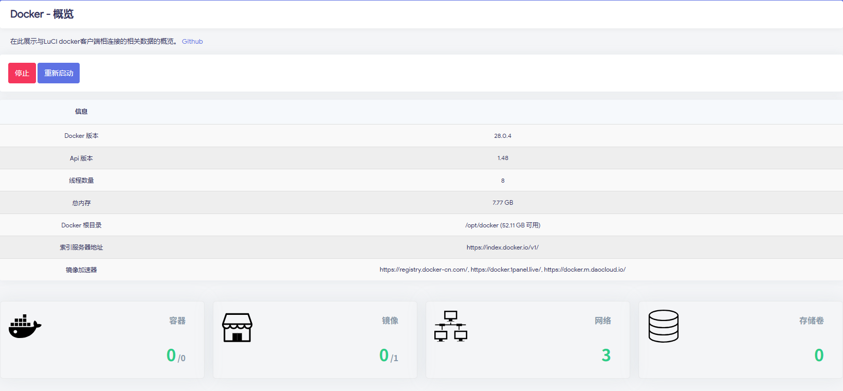
  2. After configuration, run docker pull hello-world to check whether the image can be pulled normally. If it can, the network configuration is complete. Below is an example of normal operation overview:
Common Use Cases

Jellyfin Home Theater (Emby/Plex work the same way)

Note: The following uses command-line and illustrated methods for operation examples. Subsequent chapters only provide command-line examples.

Pull Image

Execute on the command line:

# [--platform linux/arm64] is an optional parameter, can be removed
docker pull --platform linux/arm64 jellyfin/jellyfin:latest

LuCI interface operation:
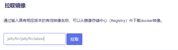
After pulling successfully, you can see it in the image list on the page, as shown below:

Start Container

Start command example:

docker run -d \
--name=jellyfin \
--restart=unless-stopped \
-p 8096:8096 \
-v /opt/data/configs/jellyfin:/config \
-v /opt/data/media:/media \
jellyfin/jellyfin:latest

You can directly copy the above command, go to the Parse CLI on the interface, click the command line button, then paste, and finally click Apply.
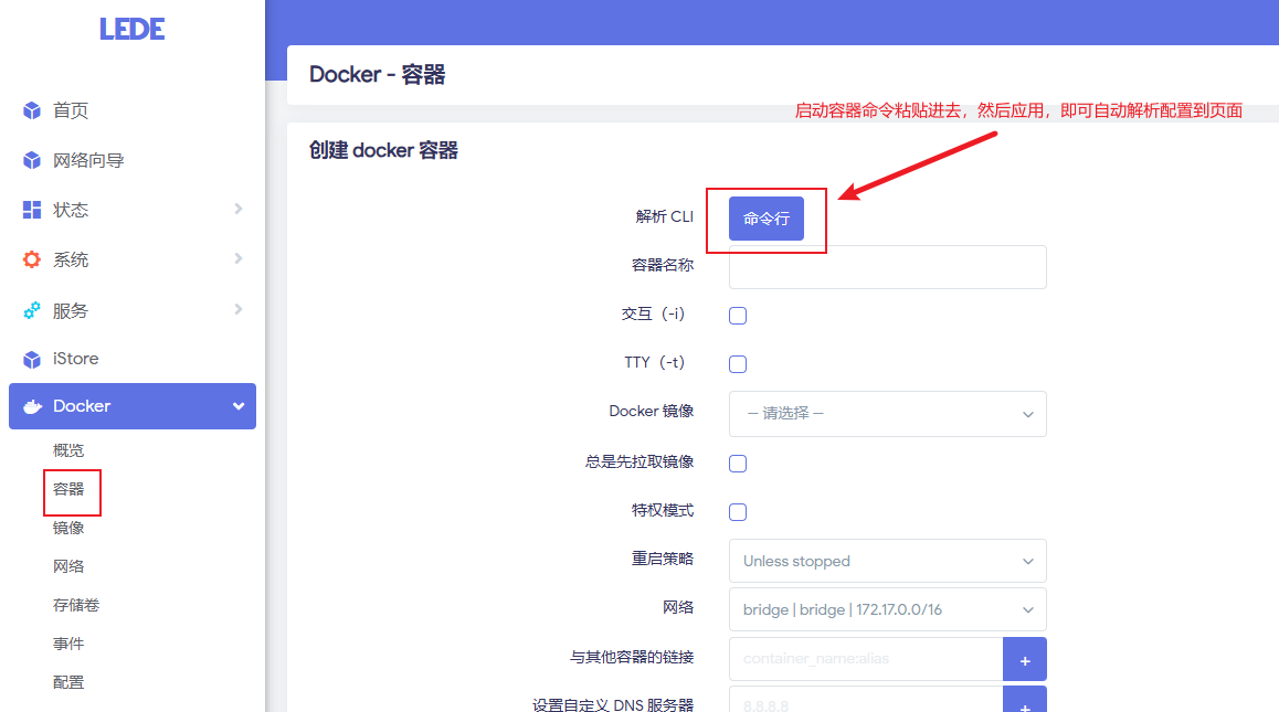
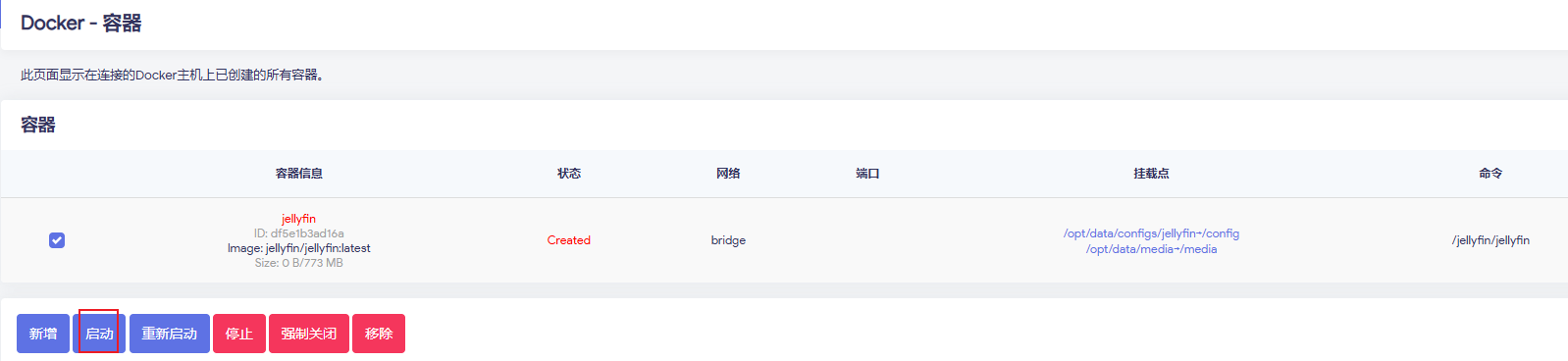
After adding, the page shows the status as Created. At this point, select the jellyfin container, then click Start:
If the SBC supports hardware decoding (and GPU drivers are set up), you can try adding:

--device /dev/dri:/dev/dri

Hardware decoding on ARM platforms is an advanced topic with many pitfalls. If it works, consider it a bonus; if not, just use pure software decoding, 1080p is generally fine.

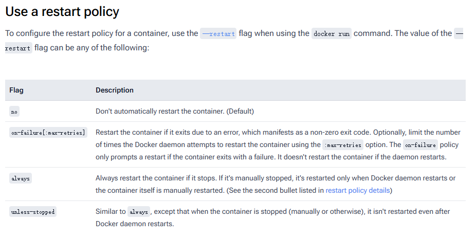
Startup parameter description:
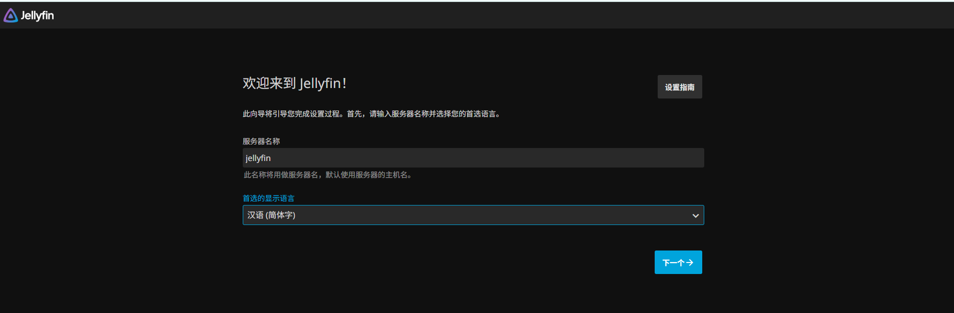
Web Configuration Process

Browser access: http://router-IP:8096

  1. Create admin account

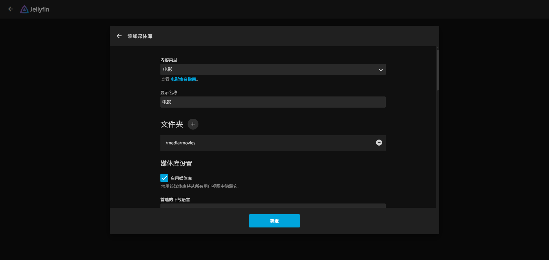
  1. Add media library:
    • Movies → /media/movies
    • TV Series → /media/tv
    • Anime → /media/anime

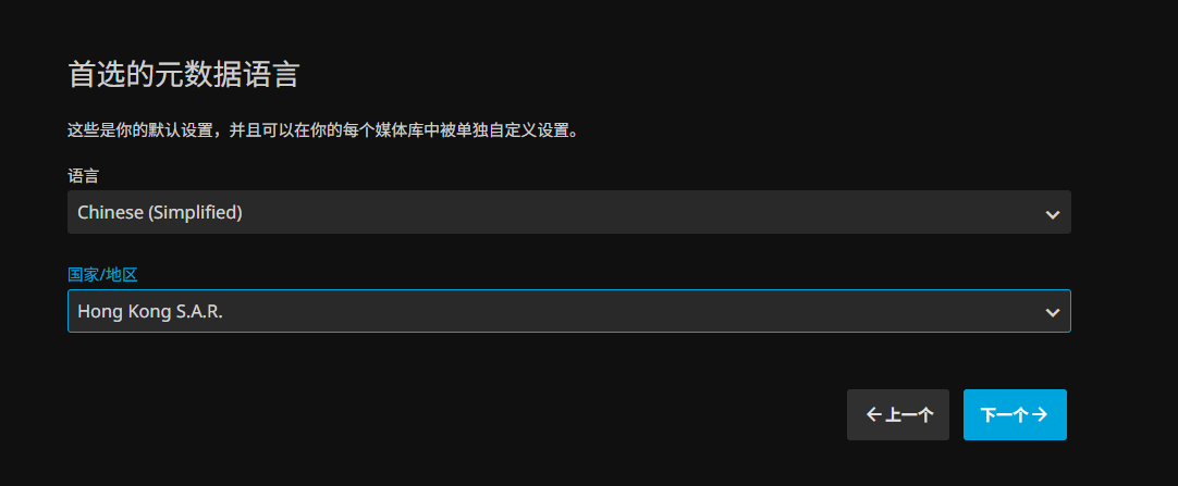
  1. Select Simplified Chinese for the language, and the metadata source can be switched to Chinese priority (smoother scraping)
After that, you can:

  • Install Jellyfin client on Android TV/TV box
  • Access directly via web/client on phone, tablet, PC
  • All terminals in the home use this ARM SBC "mini server" as the server

Usage Introduction

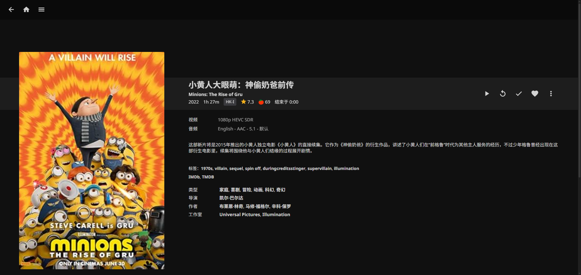
After the initial configuration above is completed, jellyfin is initialized. We log in with the configured admin account and can see the following interface:
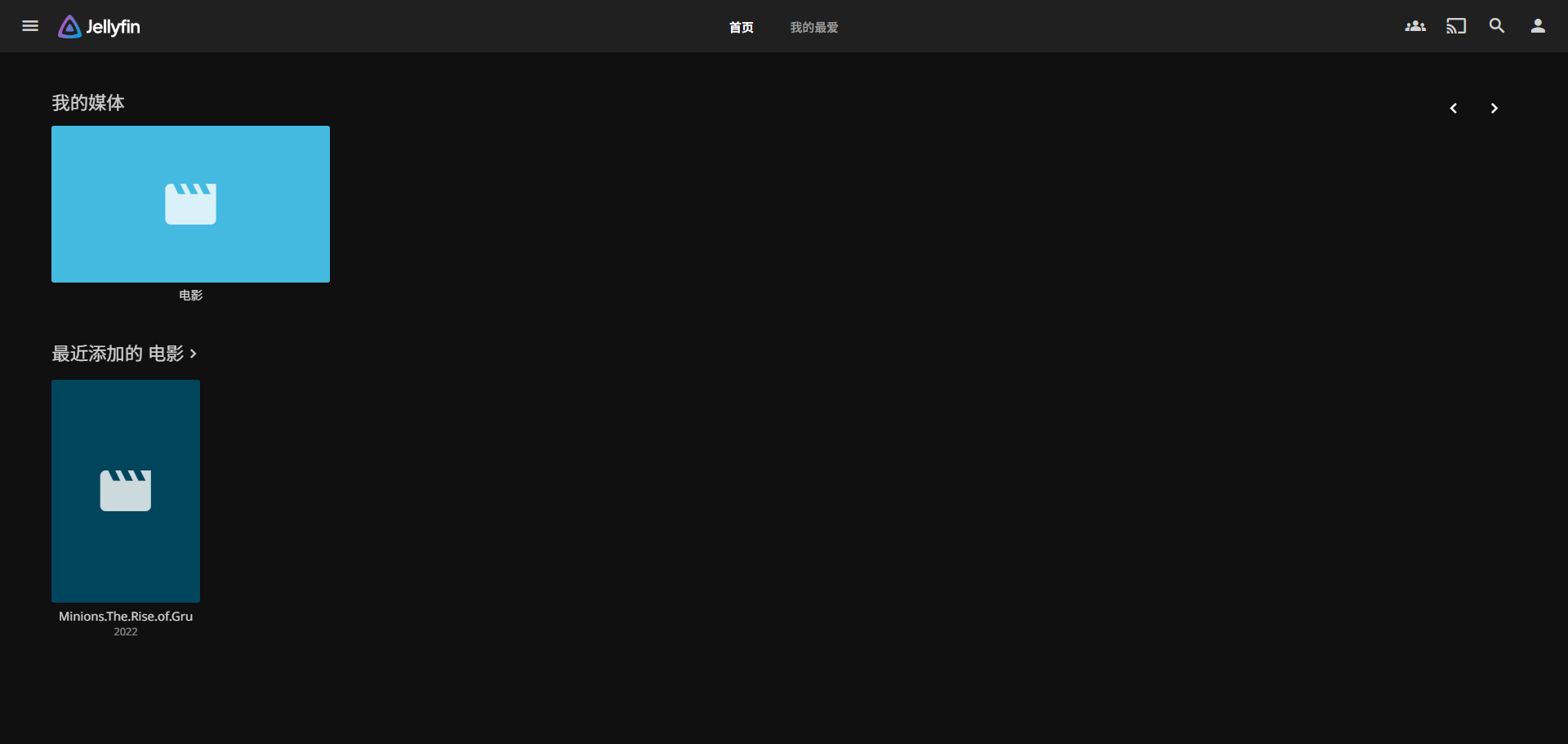
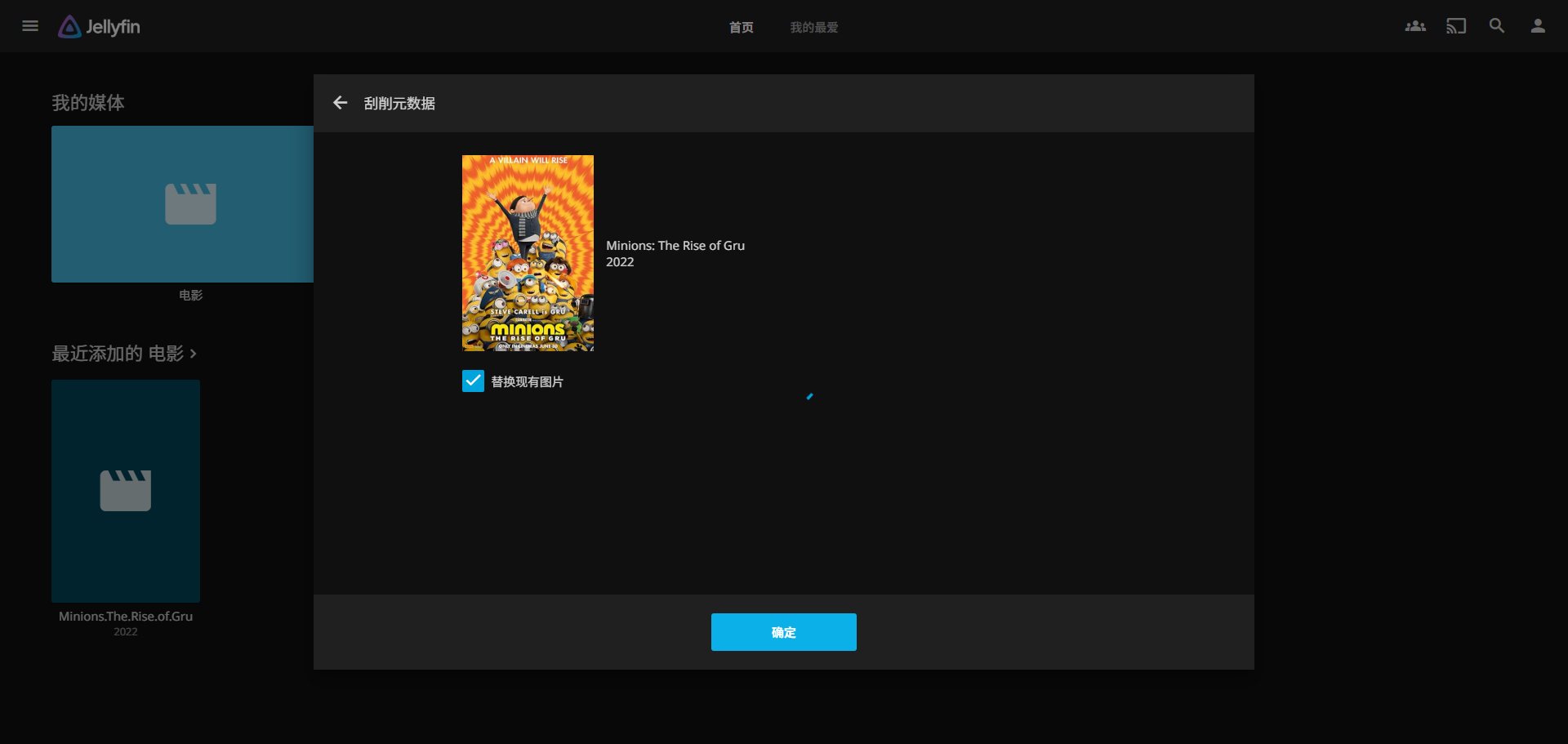
I had previously downloaded the Minions movie source via a magnet link, and now I can click to watch it online directly.

The movie has no information by default. We can scrape metadata to get cover and other information. For more use cases, please refer to jellyfin's official documentation:

Core Use Case 2: Run Ubuntu

Many services depend on a complete ubuntu environment rather than the OpenWrt plugin approach. In such cases, we can install a docker ubuntu container in the OpenWrt environment to have an environment similar to native ubuntu, enabling various custom features. Below is an example of a basic Python-implemented web server, demonstrating the powerful customization capability of running a containerized version of ubuntu.

Pull Image

Execute command:

docker pull ubuntu:24.04

Start Container

docker run -it ubuntu:24.04 bash

Command-line start example:

docker run -it -d \
--name ubt-web \
--restart=unless-stopped \
-p 8080:8000 \
ubuntu:24.04 \
bash

Enter the container and execute simple HTTP server Python code, as shown below:

docker exec -it ubt-web bash
apt update
apt install python3 python3-pip -y

cat > /srv/app.py << 'EOF'
from http.server import HTTPServer, SimpleHTTPRequestHandler

PORT = 8000
httpd = HTTPServer(("", PORT), SimpleHTTPRequestHandler)
print(f"Serving on port {PORT}...")
httpd.serve_forever()
EOF

# The web server root implemented above is the path where python3 is currently executed
python3 /srv/app.py

Web Access Test

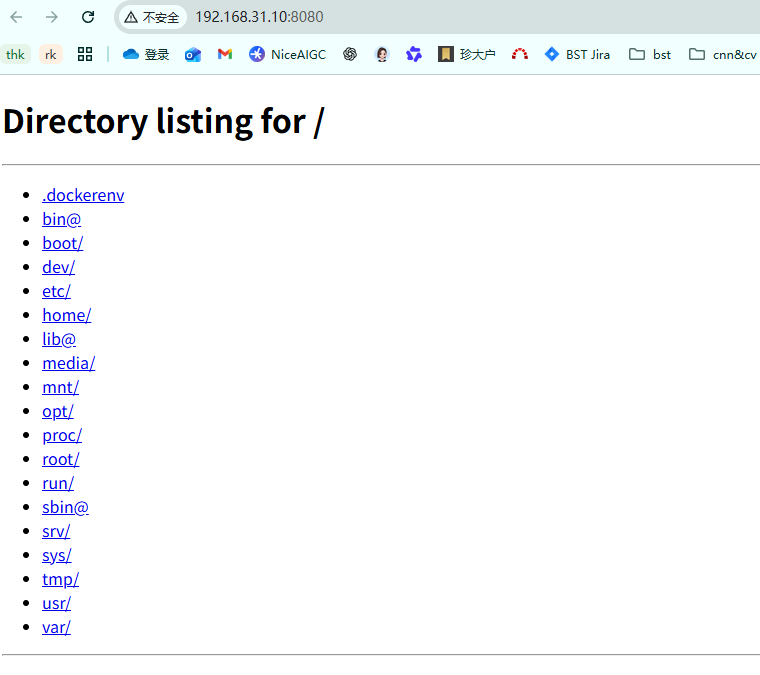
At this point, access the http server written in python in the ubuntu container via http://router-IP:8000, and a file list will appear, as shown below:
Bonus Use Case: Network-wide Ad Blocking

First, pull the adguardhome image:

docker pull adguard/adguardhome:latest

Then start the container, using AdGuard Home: network-wide DNS ad blocking

docker run -d \
--name=adguardhome \
--restart=unless-stopped \
-p 3000:3000 \
-p 53:53/tcp \
-p 53:53/udp \
-v /opt/data/config/adguard:/opt/adguardhome/conf \
-v /opt/data/config/adguard/work:/opt/adguardhome/work \
adguard/adguardhome
  • Initialization address: http://router-IP:3000
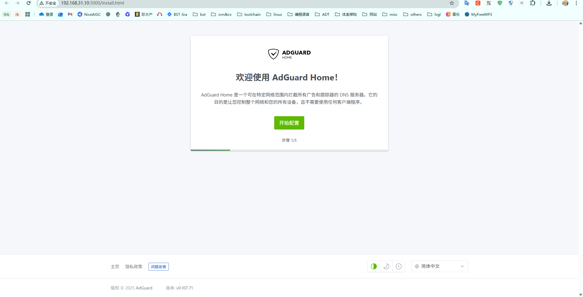
  • After configuration, in OpenWrt's LAN DHCP, point the DNS to the adguardhome container's port 53, thereby implementing DNS-based ad filtering.

For more configuration details, please refer to the AdGuard Home official documentation.

FAQ / Pitfalls Summary

Q1: How to set up external network access?

  • Recommended: Use ZeroTier/Tailscale/FRP for intranet penetration, try not to expose ports directly on the public network

Q3: How to do backups?

  • Essential: the entire /opt/data/config directory (configuration of all services)
  • Important data: /opt/data/media and downloads to keep
  • When changing machines, just connect this disk over, remount, and modify the container paths to continue using it

Q4: How to troubleshoot issues?

  • docker logs container-name to view logs
  • docker exec -it container-name /bin/sh to enter the container for troubleshooting
  • Check basic items like mount directory permissions, disk space, memory usage
Reference Links

OPENWRT System 4: Lightweight NAS Use Case Guide

· 10 min read
Yuxuan
100askTeam yuxuan.

Solution Introduction and Selection

Making the lightweight NAS (LAN file sharing) on OpenWrt accessible from the external network means being able to securely access your home storage from anywhere. This is the simplest way to set up a self-built private cloud. You only need the development board to have a USB interface, USB 3.0 is better, and then you can connect a USB portable hard drive, turning it into an OpenWrt device with lightweight NAS functionality. Below is the analysis of the implementation steps.

File Sharing

We first need to implement the LAN file sharing function. Below are the recommended methods for common LAN sharing scenarios. Here we choose samba4, FileBrowser, and webDAV, supporting all three common sharing methods. Below are the recommended protocols for specific scenarios, which you can flexibly choose according to your own scenario.

ScenarioRecommended Protocol
Windows + Linux general file sharingSamba4
Linux server mount (e.g., Docker/K8s)NFS
External network access to NAS (with frp/Tailscale)FileBrowser (Web)
Most secure transfer (requires encryption)SFTP
iPhone/macOS mount network driveWebDAV
Media player (TV, DLNA)Samba4 or NFS

Intranet Access

After completing the LAN network sharing, to implement a lightweight NAS, there is another key feature: being able to remotely view the shared files at home at any time. Then we need to implement intranet penetration. Below are common intranet penetration methods and their corresponding pros and cons. We choose to use frp (self-built relay server) and the now-popular method DDNSTO. The former requires you to have a public network server for data forwarding, while the latter is easy to operate: you only need to install the corresponding plugin, then bind your device on the Yiyouyun platform, and the Yiyouyun service provider's server will do the data forwarding.

Below is a comparison of common intranet access solutions:

SolutionProsConsSecurity
Public IP + Port MappingSimple direct connection, fastRequires public IP (ISPs generally don't provide)Low (requires firewall)
🌐 DDNS + Public IPSuitable for dynamic IP usersAlso requires public network accessMedium
🔐 ZeroTier / Tailscale VPNNo public IP needed, automatically penetrates NATRequires third-party VPN control planeHigh
☁️ frp / Cloudflare TunnelSelf-built tunnel, no public IP neededDepends on intermediate serverHigh
DDNSTO Router RemoteSimple operation, no public IP neededDepends on third-party service providerHigh

Here we prioritize using the DDNSTO plugin + the plugin provider's cloud service to implement intranet penetration for the lightweight NAS application. You can also self-build an frp cloud service on your own VPS to implement intranet penetration for the lightweight NAS application (suitable for advanced users, requires configuring many parameters and some network knowledge, of course you can also ask AI to generate the corresponding configuration). You can choose the solution that suits you according to your actual situation.

Implementing Lightweight NAS Application with DDNSTO Plugin

Mount Hard Drive

First, we need to insert the portable hard drive into the USB TYPE-A port of DshanPi A1, then configure the corresponding mount directory, and set it to automatically mount on every boot. Here we use a USB flash drive for the test example; the configuration method for a portable hard drive is exactly the same.

First, on the System -> Mount Points page, configure the directory for automatic disk mounting, and enable it.

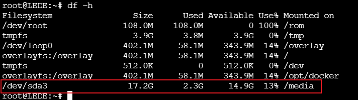
After configuration, restart the device and observe whether the configuration remains valid after power off. If it takes effect, you can see the following print:

Default permissions of /media:

Enable File Sharing Service

Samba Sharing

Samba is a free software that implements the SMB protocol on Linux systems. We can use terminal devices that support the SMB protocol to implement file sharing within the LAN.

Install Samba

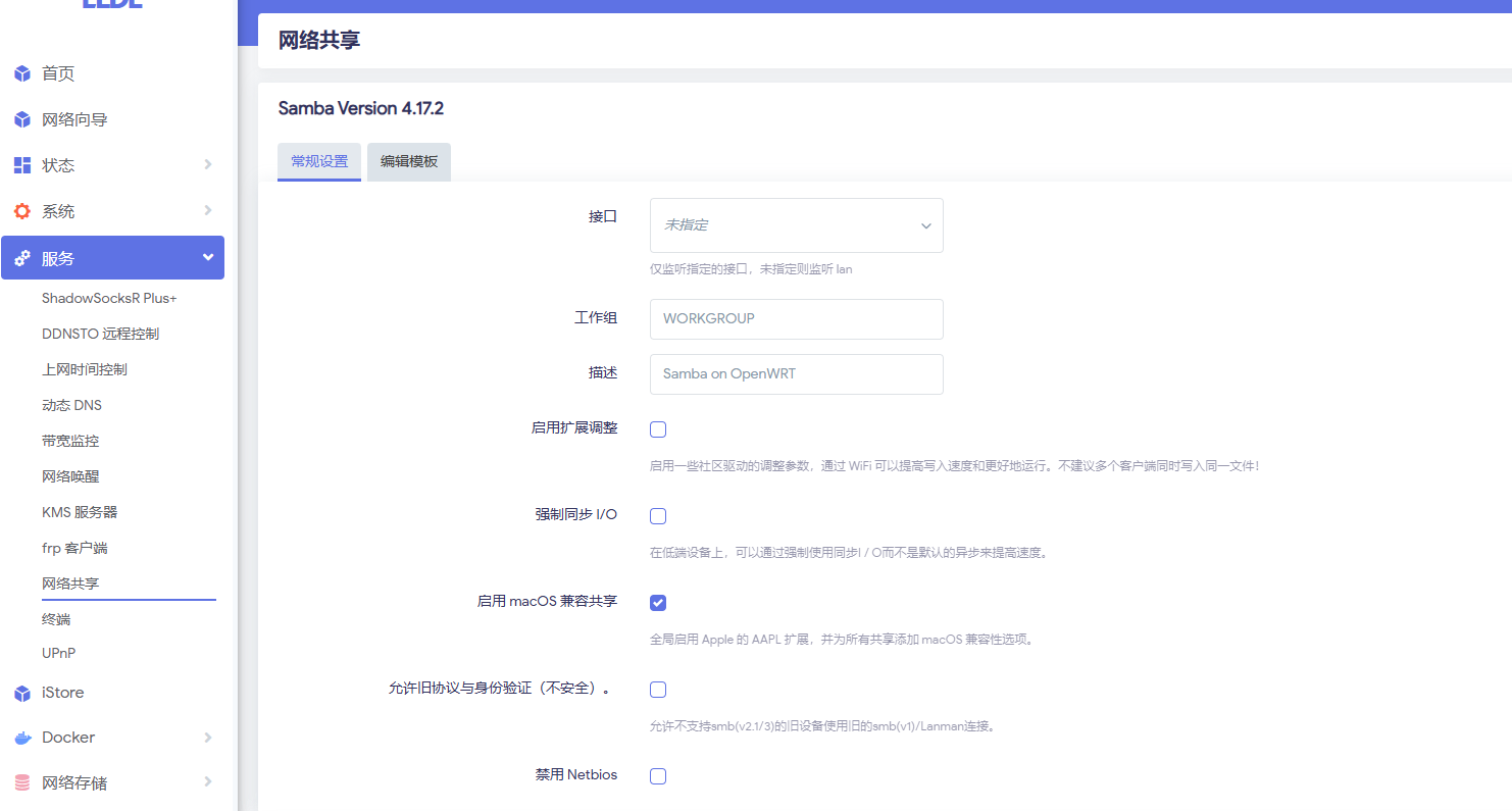
First, we need to select luci-app-samba4 before compiling, or install the samba4 server program into the system by installing ipk online after flashing. After installation, on the page: Services -> Network Shares you can see the corresponding configuration, as shown below:

Create Samba User

When performing network sharing, we should avoid using the root user to log in to the samba server. To this end, we separately create a user for accessing the samba server and grant it access permissions to the folder.

Open Services -> Terminal, execute the following commands to create a user, and grant the user access permissions to the shared directory.

#Add a user named samba
useradd samba

#Create an smb service password for user samba, this is separate from the user's login password, they can be different
smbpasswd -a samba

#Grant user samba access to the shared directory
#Note: Only ext4 file systems can modify permissions, make corresponding adjustments according to your disk format
chown -R samba:samba /media/

Modify /etc/passwd to configure the samba user so it cannot log in. Below is an example:

Modify samba4 Configuration

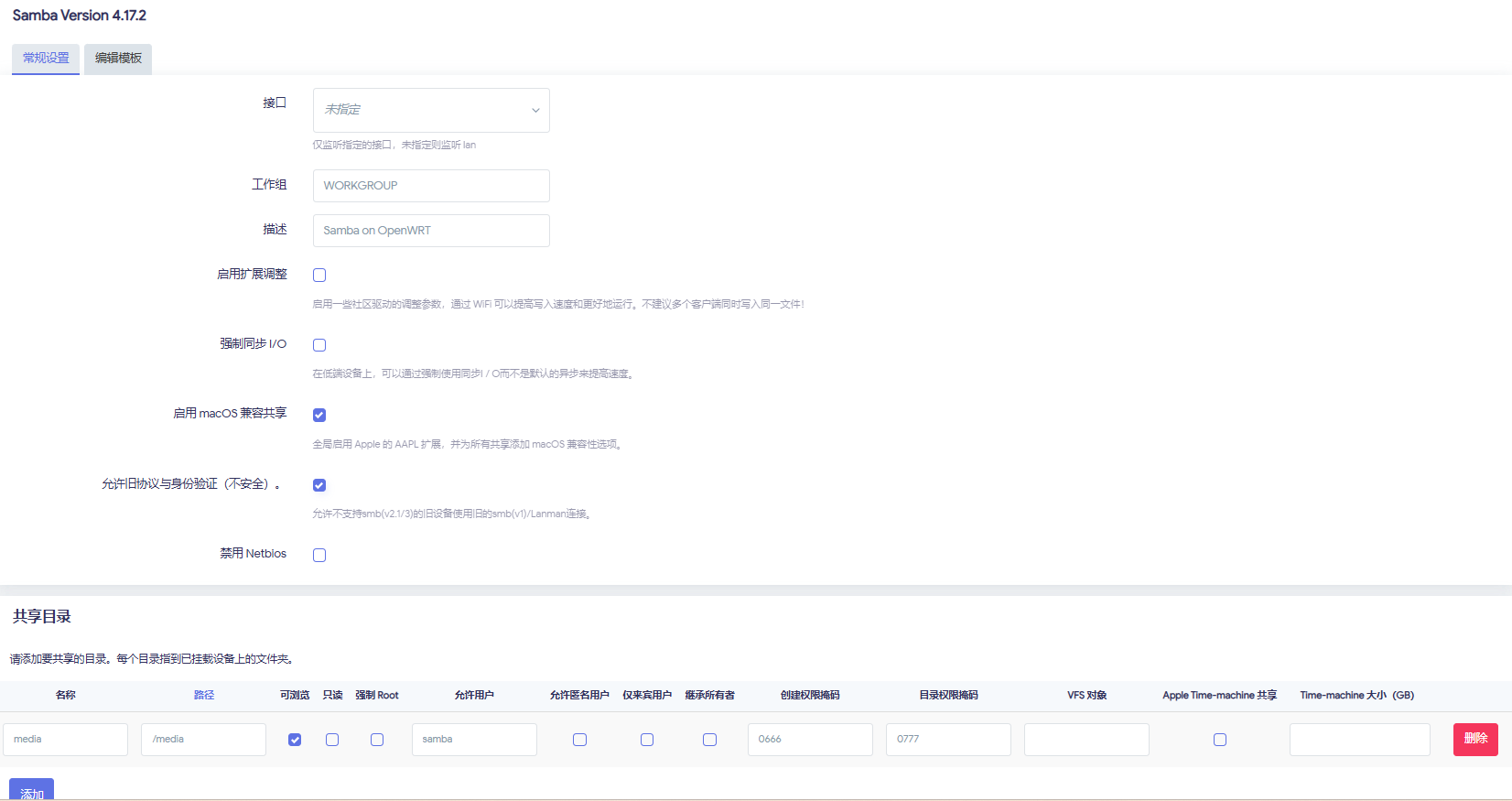
Open Services -> Network Shares to configure parameters.

Select the interface as lan, so that intranet devices can access it. Check Allow legacy protocols and authentication.

Click Add an entry.

  • Name: The folder name displayed when sharing, can be set freely, here set to media
  • Path: The folder path to be shared, here set to the directory mounted in the previous chapter<font style={{color: 'rgb(64, 64, 64)', backgroundColor: 'rgb(252, 252, 252)'}}>/media</font>
  • Allowed users: Users with access permissions, here set to the user samba just created.
These are the main settings. Save and apply these configurations. For other settings, you can explore other advanced configurations on your own.

SFTP Sharing

Install SFTP Server

Dropbear does not support SFTP, but it supports calling an external sftp-server.

OpenWrt already provides a standalone openssh-sftp-server package:

opkg update
opkg install openssh-sftp-server

After installation, sftp-server will be placed at: /usr/lib/sftp-server. This solution is suitable for scenarios where you need a GUI to configure ssh keys but also need sftp server functionality. If you replace everything with the full OpenSSH suite, since OpenSSH has no official LuCI configuration interface in OpenWrt, all configurations would have to be done through the terminal.

Configure SFTP

After installation, you can use it directly without other configuration. For example, connecting directly with Xftp, you can see the files in the system.

WebDAV Sharing

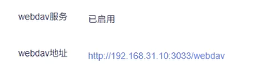
After installing the DDNSTO plugin, it comes with a lightweight webdav service built in. You don't need to install it separately, just use it directly.

Configure Intranet Penetration

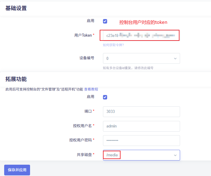
First, log in to the DDNSTO console. After registering and logging in, record the user Token, then configure the DDNSTO remote control page on the board side, configuring the corresponding parameters. An example is as follows:

Configure Samba Remote Access

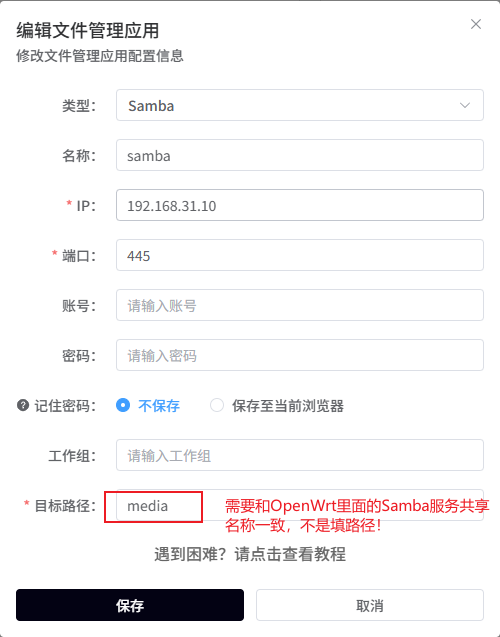
Log in to the DDNSTO console. Under the File Management section, click Add File Management to add a Samba protocol file management service. Fill in the corresponding parameters. An example is as follows:

  1. Add configuration

  1. Click Connect
  2. Enter the user and password from the Samba4 configuration
  3. Connection successful, you can see the files in the corresponding directory, as shown below:

Configure SFTP Remote Access

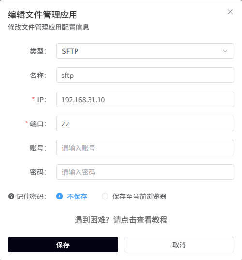
Log in to the DDNSTO console. Under the File Management section, click Add File Management to add an Sftp protocol file management service. Fill in the corresponding parameters. An example is as follows:

  1. Add configuration

  1. Click Access

  1. Enter the username and password that can log in via ssh, here enter the password for root
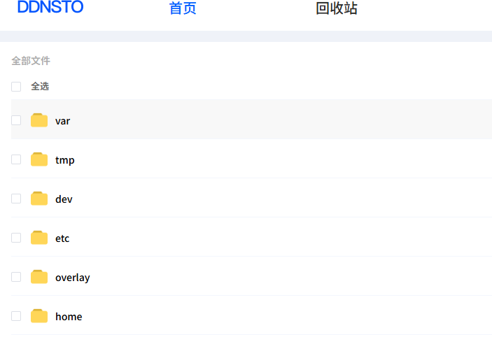
  2. Connection successful, you can see the files in the corresponding directory, as shown below:

Configure WebDAV Remote Access

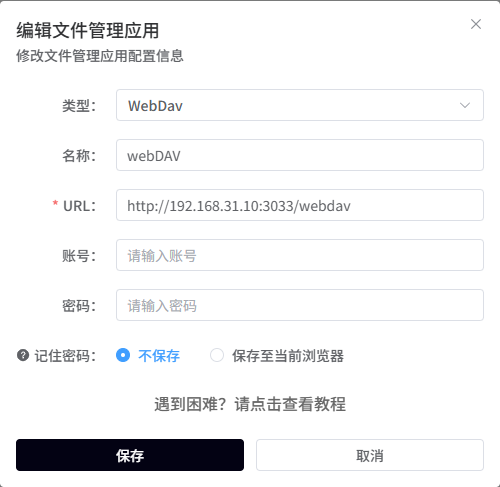
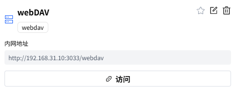
Log in to the DDNSTO console. Under the File Management section, click Add File Management to add a webdav protocol file management service. Fill in the corresponding parameters. An example is as follows:

  1. Add configuration

  1. Click Access

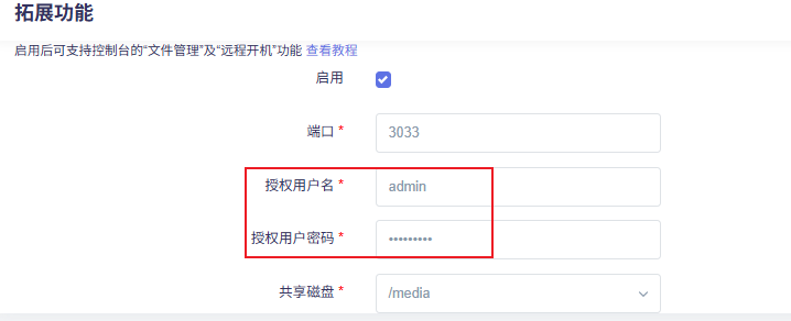
  1. Enter the authorized username and password filled in the DDSNTO plugin in the router system to the login page

  1. Connection successful, you can see the files in the corresponding directory, as shown below:

Configure Remote Access to Router Backend

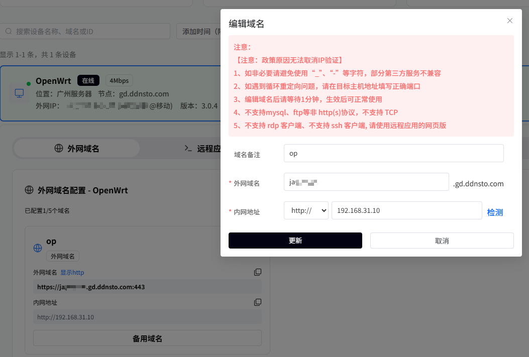
Log in to the DDNSTO console, select the External Domain section, then click Add Domain, and fill in the configuration according to the example below:

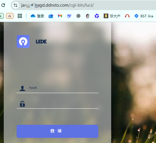
After configuration, click the External Domain section to jump directly to the external domain page. This way you can remotely configure the router in the LAN from anywhere.

To summarize: The DDNSTO plugin integrates many remote scenarios. For light use, the paid 4Mbps plan is sufficient, with low latency, saving you from various complex environment setup processes and the cumbersome process of self-building a VPS. Recommended!

Self-build Frp Cloud Service to Implement Lightweight NAS Application

Mount Hard Drive and Enable File Sharing Service

The mounting of the hard drive and enabling of the file sharing service in the self-built solution are exactly the same as the DDNSTO plugin method. For detailed steps, please refer to the content in the previous chapter, which will not be repeated here.

Configure Intranet Penetration Service

There are many parameters to configure here, and security needs to be considered. There are many configuration items and certificate steps involved. Due to space limitations, it will not be described in detail here. For more information, please refer to frp's official documentation to set up the corresponding intranet penetration service.

OPENWRT System 3: Existing Feature Optimization

· 15 min read
Yuxuan
100askTeam yuxuan.

After downloading the officially adapted OpenWrt source code from 100ask, I found that many features were not fully adapted, causing some poor user experience during use. Below is a record of the problems I found during use and an analysis of the solutions, hoping to give readers some ideas for solving similar problems. Since my knowledge is limited, if there are any errors, you are welcome to discuss.

Installing third-party ipk does not work

The libc of the default cloud mirror repository uses musl. After flashing with glibc, I found that all installed programs could not be used. The default OpenWrt uses musl libc.

Installing third-party fdisk does not work

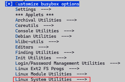
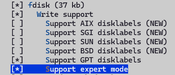
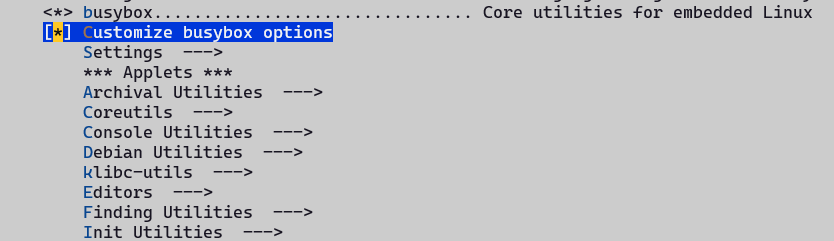
With the default busybox configuration, many tools are missing. After installing fdisk through opkg, it prompts that a certain library does not exist. You need to manually configure the Busybox options. We turn on the custom busybox options, then enable fdisk.

Then recompile the image and flash it. After testing, you can find that fdisk works now.

sysupgrade image does not work

When using the default generated sysupgrade image, in the interface [System - Backup / Upgrade - Flash new firmware image], after selecting the compiled firmware, I found it could not be used, with the following error print messages:

Tue Dec  2 17:27:21 2025 user.info upgrade: Device 100ask,dshanpi-a1 not supported by this image
Tue Dec 2 17:27:21 2025 user.info upgrade: Supported devices: 100ask,dshanpia1
Tue Dec 2 17:27:21 2025 user.info upgrade: Reading partition table from bootdisk...
Tue Dec 2 17:27:22 2025 user.info upgrade: Reading partition table from image...
Tue Dec 2 17:27:22 2025 user.info upgrade: Device 100ask,dshanpi-a1 not supported by this image
Tue Dec 2 17:27:22 2025 user.info upgrade: Supported devices: 100ask,dshanpia1
Tue Dec 2 17:27:22 2025 user.info upgrade: Reading partition table from bootdisk...
Tue Dec 2 17:27:22 2025 user.info upgrade: Reading partition table from image..

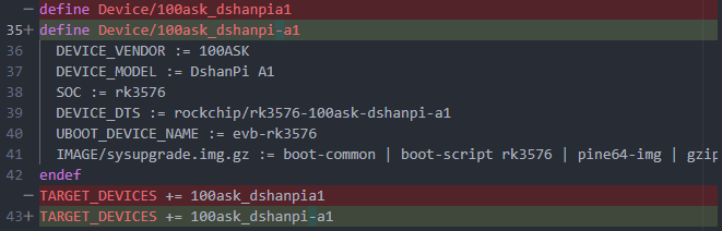
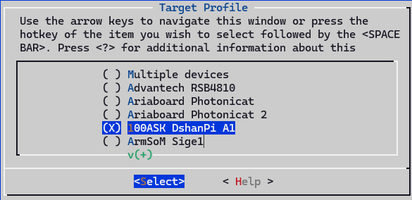
After checking, I found that the device name defined in armv8.mk is inconsistent with the compatible in the dts, causing sysupgrade to refuse flashing.

OpenWrt sysupgrade will read:

  1. The identifier of the currently running device:

From:

  • /proc/device-tree/compatible
  • /etc/board.json
  1. The supported_devices list embedded in the firmware

If any character of the two does not match, it reports: Device XXX not supported by this image

Now that we know the problem, the fix is simple. Modify as follows:

  1. Modify target/linux/rockchip/image/armv8.mk to keep it consistent with the dts

  1. Re-run make menuconfig, select the target, and the .config file will be updated automatically

  1. Re-run make V=s -j8 to build the image.

sftp does not work

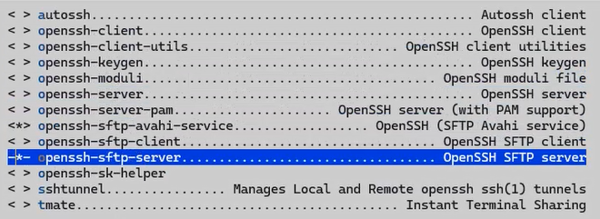
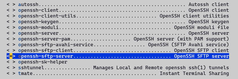
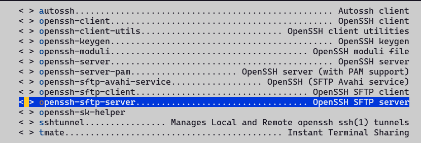
By default, dropbear is used as the ssh server, which does not have sftp functionality. Here we modify the configuration, turn off dropbear, and then enable openssh under Network -> SSH, as shown below.

The build fails, openssh-sk-helper build depends on libfido2. We manually enable this library, select it as y, then recompile.

Note: openssh-server and openssh-server-pam cannot be enabled at the same time. We just enable the build without PAM support.

rootfs space is too small

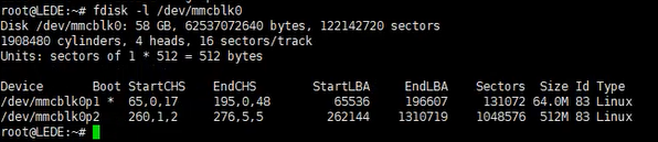
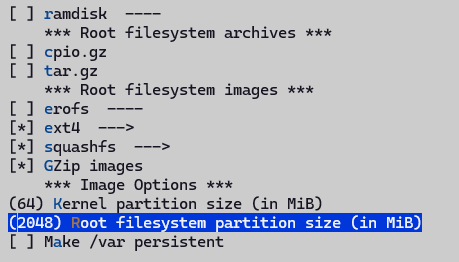
We prefer to flash the squashfs format image, which makes it convenient to restore factory configuration, because the rom in squashfs format is based on overlayfs, and updated configurations will not directly modify the content in the rom. However, we can find that the default configured rootfs size is relatively small, while the onboard EMMC has 58G. We can expand the rootfs space to 8G, and allocate the remaining space as a separate partition.

The default configured rootfs partition is 512M, as shown below:

Modify the configuration, set the default rootfs partition size to 2G, modify the Rootfs partition size configuration under Target Images, as shown below:

USB device cannot be recognized

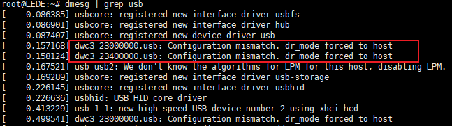
When we simply enable usb0 and usb1 in the device tree, we find that USB drives can be recognized, but during the usb driver probe, it prints that dr_mode is forcibly set to host. Looking at the code, we find that the default configuration is otg, but there is no corresponding otg configuration, and the drd-related code is not compiled.

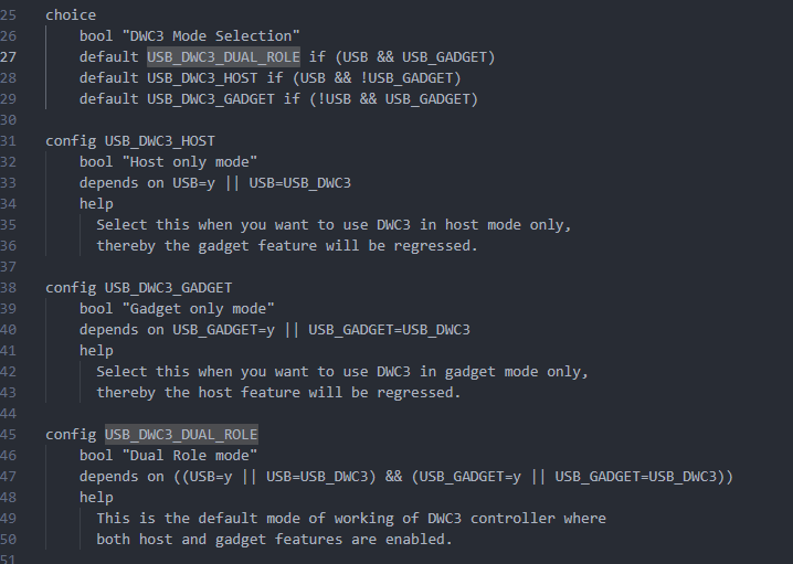
We need to modify the device tree file to enable the usb0 and usb1 controllers, with the default role as host. Enable the DRD ROLE SWITCH feature, then you can dynamically configure the controller role, and you can also specify the default role.

You must enable USB Gadget to enable the dual-role function, so we turn it on, then select Dual Role mode in Mode Selection. This will generate the usb_role sysfs node in the kernel, which can be dynamically configured as host or peripheral. On the DshanPi A1, usb1 is fixed as host, and usb0 can be configured as dual-role and can be switched. So we make the following dts configuration:

--- a/target/linux/rockchip/files/arch/arm64/boot/dts/rockchip/rk3576-100ask-dshanpi-a1.dts
+++ b/target/linux/rockchip/files/arch/arm64/boot/dts/rockchip/rk3576-100ask-dshanpi-a1.dts
@@ -770,6 +770,20 @@
status = "okay";
};

+// usb0 as type-c port, can be host or peripheral.
+&usb_drd0_dwc3 {
+ status = "okay";
+ usb-role-switch;
+ role-switch-default-mode ="host";
+};
+
+// usb1 as type-a port, fixed to host
+&usb_drd1_dwc3 {
+ status = "okay";
+ usb-role-switch;
+ role-switch-default-mode ="host";
+};
+
&uart0 {
pinctrl-0 = <&uart0m0_xfer>;
status = "okay";

After configuration, usb1 can be used, but usb0 cannot. And the onboard Hynetik HUSB311 Type-C chip can provide USB PD and USB Type-C functionality. We found that the default 6.12 kernel version driver does not support this chip. Checking the official rockchip repository, there is support for this chip, which needs to be ported over. We temporarily don't need the DP function, so we mask it out.

PWM fan always runs at maximum speed

After power on, the fan always runs at maximum speed, which is quite loud. We need to modify it to support automatic speed adjustment based on temperature, which is more suitable for common application scenarios. The troubleshooting record is as follows:

Check hardware

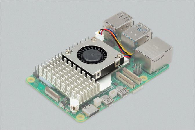
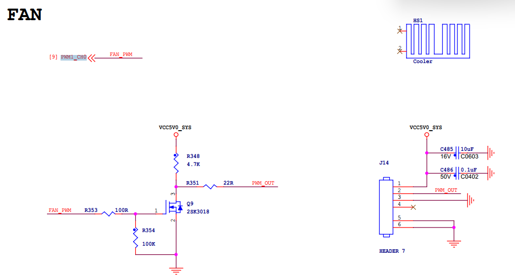
The fan uses the Raspberry Pi 5 4-pin fan, which is a standard 4-pin JST connector. The physical photo and schematic are as follows:

The fan connector is a 1mm pitch JST SH socket with four pins:
PIN NumberFunction
1+5V
2PWM
3GND
4Speed

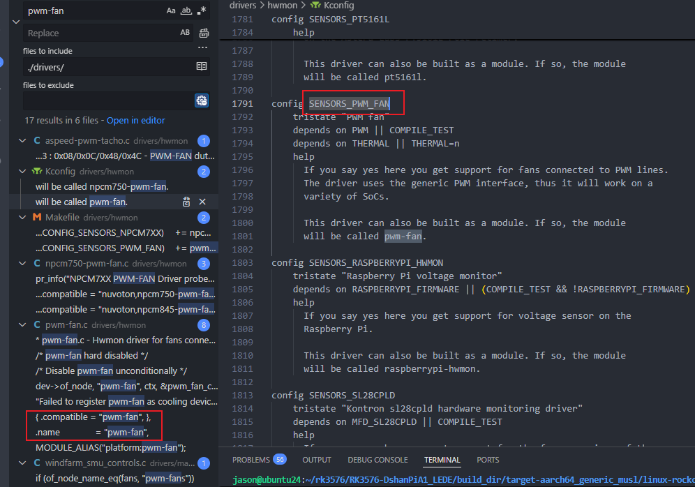
After checking the manual, pin 2 is connected to PWM1, and pin 4 is connected to the fan speed port, which means it does not support reading the speed, and can only control the speed via PWM. Looking at the schematic, it is PWM1_CH0, and there is a corresponding configuration in the dts. Searching the driver according to the compatible field "pwm-fan", I found that the file linux-6.12.43/drivers/hwmon/pwm-fan.c exists but was not compiled. That means the KCONFIG was not selected, and the pwm-fan driver was not compiled.

Enable PWM driver

So we directly run make kernel_menuconfig, search for CONFIG_SENSORS_PWM_FAN, then enter the number corresponding to the search result, and it will jump directly to the corresponding configuration location. Just enter Y to enable it.

After compiling and flashing, during the boot process, I found that the pwm-fan driver failed to start, with the following print:

It can be concluded that the upstream PWM device was not found. Searching the compatible of the referenced node, I found that the corresponding driver was not enabled, in a separate directory: drivers/soc/rockchip

The enabled drivers:

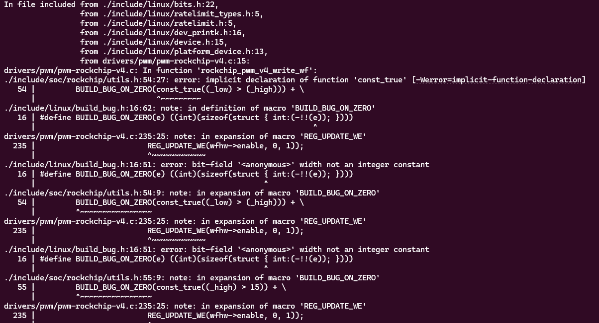
After enabling, there will be compilation issues. We modify as follows:

Modify as follows:

--- a/include/soc/rockchip/utils.h	2025-11-23 03:35:07.695086227 +0800
+++ b/include/soc/rockchip/utils.h 2025-11-23 03:34:43.946599951 +0800
@@ -50,6 +50,7 @@
*
* Return: the value, shifted into place, with the required write-enable bits
*/
+#if 0
#define REG_UPDATE_WE(_val, _low, _high) ( \
BUILD_BUG_ON_ZERO(const_true((_low) > (_high))) + \
BUILD_BUG_ON_ZERO(const_true((_high) > 15)) + \
@@ -57,6 +58,11 @@
BUILD_BUG_ON_ZERO(const_true((u64) (_val) > U16_MAX)) + \
((_val & GENMASK((_high) - (_low), 0)) << (_low) | \
(GENMASK((_high), (_low)) << 16)))
+#else
+#define REG_UPDATE_WE(_val, _low, _high) ( \
+ ((_val & GENMASK((_high) - (_low), 0)) << (_low) | \
+ (GENMASK((_high), (_low)) << 16)))
+#endif

/**
* REG_UPDATE_BIT_WE - update a bit with a write-enable mask
@@ -68,9 +74,14 @@
*
* Return: a value with bit @__bit set to @__val and @__bit << 16 set to ``1``
*/
+#if 0
#define REG_UPDATE_BIT_WE(__val, __bit) ( \
BUILD_BUG_ON_ZERO(const_true((__val) > 1)) + \
BUILD_BUG_ON_ZERO(const_true((__val) < 0)) + \
REG_UPDATE_WE((__val), (__bit), (__bit)))
+#else
+#define REG_UPDATE_BIT_WE(__val, __bit) ( \
+ REG_UPDATE_WE((__val), (__bit), (__bit)))
+#endif

#endif /* __SOC_ROCKCHIP_UTILS_H__ */

Method to configure speed

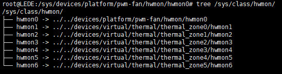
The method to manually configure pwm-fan: find the pwm-fan directory under sysfs, enter /sys/class/hwmon/hwmon0/, and you can see two files pwm1_enable and pwm1. First configure pwm1 to 100, and observe whether the fan noise decreases. The experiment found that it indeed became quieter, which means the PWM control took effect.

root@LEDE:~# ls /sys/class/hwmon/hwmon0/
device of_node pwm1 subsystem
name power pwm1_enable uevent
root@LEDE:~# echo 100 > /sys/class/hwmon/hwmon0/pwm1

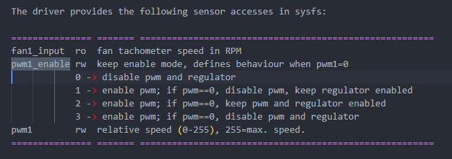
kernel documentation about pwm_fan sysfs node description

Reference documents:

  • Documentation/hwmon/pwm-fan.rst
  • Documentation/devicetree/bindings/hwmon/pwm-fan.yaml
  • Documentation/driver-api/thermal/sysfs-api.rst

You can also find pwm-fan through the cooling_device under the thermal framework. Under the thermal cooling device framework, there is a registered sysfs interface, corresponding to the ops provided by the pwm_fan driver binding. The state value corresponds to the index of the cooling_levels array configured in the dts, so you can configure the corresponding relative speed in the pwm driver by configuring a value from 0..max_state, directly in the shell.

static const struct thermal_cooling_device_ops pwm_fan_cooling_ops = {
.get_max_state = pwm_fan_get_max_state,
.get_cur_state = pwm_fan_get_cur_state,
.set_cur_state = pwm_fan_set_cur_state,
};

//dts
fan: pwm-fan {
status = "okay";
compatible = "pwm-fan";
#cooling-cells = <2>;
pwms = <&pwm1_6ch_0 0 50000 1>;

// This corresponds to states from 0..5
cooling-levels = <0 100 125 150 200 255>;

// The trips configured here did not take effect. We need to put them into the thermal framework
rockchip,temp-trips = <
40000 1
50000 2
60000 3
65000 4
70000 5
>;
};
root@LEDE:~# ls /sys/class/thermal/cooling_device0/
cur_state max_state power subsystem type uevent
root@LEDE:~# cat /sys/class/thermal/cooling_device0/max_state
5
# This is equivalent to echo 100 > /sys/class/hwmon/hwmon0/pwm1
root@LEDE:~# echo 1 > /sys/class/thermal/cooling_device0/cur_state

Add automatic speed adjustment feature

Automatic speed adjustment relies on the thermal system, mainly consisting of thermal_zone, cooling_device, and trip_point.

Reference article: Linux Thermal Framework Analysis - CSDN Blog

Add the corresponding trip under the thermal_zones node configured in the original dts.

Compiling dts separately failed

make target/linux/prepare V=s
make target/linux/compile DTBS=1 V=s

Then you can directly find the generated:

build_dir/target-*/linux-*/linux-*/arch/arm64/boot/dts/*.dtb

When configuring pwm1 or cur_state=0, the fan speed is maximum. According to the kernel documentation about the pwm_fan sysfs node, the specific behavior when pwm1=0 can be configured via the pwm1_enable file. The default value is 1, i.e., disable pwm, keep regulator enabled. So when set to 0, it will directly go to full speed.

So when we configure the cooling-levels array, we set the value of the 0th element to 10, so that it rotates at a lower speed. Then set pwm1_enable to 2, which means when pwm=0, both pwm and regulator still have output, i.e., duty cycle 0.

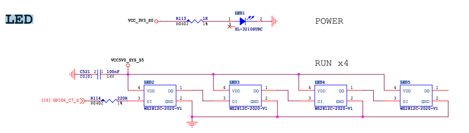
Onboard LED has no driver

This is a RGB LED strip chain controlled by single-wire serial:

  • Chip: WS2812C-2020
  • Number of LEDs: 4 (RUN × 4)
  • Each LED is both an RGB LED and integrates a driver chip
  • Only 1 GPIO digital signal line is needed to control a string of LEDs

Typical uses:

  • Status light
  • Marquee light
  • Motherboard lighting
  • Industrial control indicator light
  • Router/TV box breathing light

WS2812 uses single-wire 800kHz NRZ protocol, not ordinary PWM. The Linux kernel cannot bit-bang fast enough directly, and must use something that can generate precise waveforms to drive it.

By searching the source code, I found that the project provides two drivers: one is leds-ws2812b, and the other is ws2812-pio-rp1. After careful inspection, I found that one is based on SPI, and the other is based on the PIO expansion chip method. In our schematic, we can only use the spi hacking method.

The configuration method refers to the redmi configuration, just adapt it to dshanpi.

The PIN in the schematic does not have MOSI function, so SPI HACKING cannot be used. After consultation, we need to use the PWM HACKING method.

MMC driver frequently prints errors

Driver error messages:

[ 1344.988178] mmc0: Timeout waiting for hardware interrupt.
[ 1344.988672] mmc0: sdhci: ============ SDHCI REGISTER DUMP ===========
[ 1344.989235] mmc0: sdhci: Sys addr: 0x00000002 | Version: 0x00000005
[ 1344.989800] mmc0: sdhci: Blk size: 0x00007200 | Blk cnt: 0x00000002
[ 1344.990364] mmc0: sdhci: Argument: 0x00069e72 | Trn mode: 0x0000003f
[ 1344.990929] mmc0: sdhci: Present: 0x03f700f1 | Host ctl: 0x00000035
[ 1344.991493] mmc0: sdhci: Power: 0x0000000d | Blk gap: 0x00000000
[ 1344.992057] mmc0: sdhci: Wake-up: 0x00000000 | Clock: 0x0000030f
[ 1344.992621] mmc0: sdhci: Timeout: 0x0000000e | Int stat: 0x00000000
[ 1344.993185] mmc0: sdhci: Int enab: 0x03ff000b | Sig enab: 0x03ff000b
[ 1344.993749] mmc0: sdhci: ACmd stat: 0x00000000 | Slot int: 0x00000000
[ 1344.994313] mmc0: sdhci: Caps: 0x3a6dc881 | Caps_1: 0x08000007
[ 1344.994876] mmc0: sdhci: Cmd: 0x0000123a | Max curr: 0x00000000
[ 1344.995439] mmc0: sdhci: Resp[0]: 0x00000900 | Resp[1]: 0xfff6dbff
[ 1344.996003] mmc0: sdhci: Resp[2]: 0x320f5903 | Resp[3]: 0x00009001
[ 1344.996566] mmc0: sdhci: Host ctl2: 0x0000380f
[ 1344.996957] mmc0: sdhci: ADMA Err: 0x00000060 | ADMA Ptr: 0x00000000fc300210
[ 1344.997581] mmc0: sdhci: ============================================

Probe information in dmesg:

[ 0.438699] mmc0: SDHCI controller on 2a330000.mmc [2a330000.mmc] using ADMA 64-bit
[ 0.499319] mmc0: new HS400 Enhanced strobe MMC card at address 0001
[ 0.500422] mmcblk0: mmc0:0001 CJNB4R 58.2 GiB
[ 0.502009] mmcblk0: p1 p2 p3
[ 0.502655] mmcblk0boot0: mmc0:0001 CJNB4R 4.00 MiB
[ 0.503828] mmcblk0boot1: mmc0:0001 CJNB4R 4.00 MiB
[ 0.504873] mmcblk0rpmb: mmc0:0001 CJNB4R 4.00 MiB, chardev (247:0)

Based on AI search and the information in the DTS, it can be seen that the eMMC works completely normally during the power-on initialization stage. The controller registers/clock/reset/pinctrl are basically fine, otherwise it would not have successfully switched to HS400 ES and recognized partitions.

We can try downgrading to HS200 or reducing the frequency for testing, to find a stable working version. I tested two methods locally:

  1. Downgrade to HS200, without changing frequency
mmc-hs200-1_8v;
//mmc-hs400-1_8v;
//mmc-hs400-enhanced-strobe;

After testing, HS200 works fine, boot print:

[    0.439179] mmc0: SDHCI controller on 2a330000.mmc [2a330000.mmc] using ADMA 64-bit
[ 0.492249] mmc0: new HS200 MMC card at address 0001
[ 0.493187] mmcblk0: mmc0:0001 CJNB4R 58.2 GiB
[ 0.494771] mmcblk0: p1 p2 p3
[ 0.495416] mmcblk0boot0: mmc0:0001 CJNB4R 4.00 MiB
[ 0.496586] mmcblk0boot1: mmc0:0001 CJNB4R 4.00 MiB
[ 0.497629] mmcblk0rpmb: mmc0:0001 CJNB4R 4.00 MiB, chardev (247:0)

  1. Keep HS400 unchanged, reduce frequency to 100M
//max-frequency = <200000000>;
max-frequency = <100000000>; //work perfect on 100M

After testing, it also works normally, boot print:

[    0.439264] mmc0: SDHCI controller on 2a330000.mmc [2a330000.mmc] using ADMA 64-bit
[ 0.492185] mmc0: new HS400 Enhanced strobe MMC card at address 0001
[ 0.493275] mmcblk0: mmc0:0001 CJNB4R 58.2 GiB
[ 0.494696] mmcblk0: p1 p2 p3
[ 0.495331] mmcblk0boot0: mmc0:0001 CJNB4R 4.00 MiB
[ 0.496498] mmcblk0boot1: mmc0:0001 CJNB4R 4.00 MiB
[ 0.497546] mmcblk0rpmb: mmc0:0001 CJNB4R 4.00 MiB, chardev (247:0)

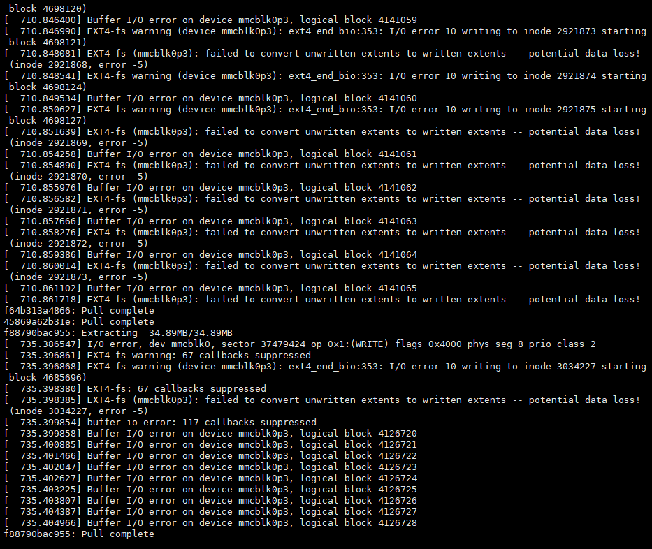
But I found that when using docker, there are various error prints:

So I'll use the minimal modification method: remove the HS400 mode configuration in the device tree and set the HS200 mode. Testing shows stable operation, so I'll use this for now.

OPENWRT System 2: Building a Custom System

· 10 min read
Yuxuan
100askTeam yuxuan.

Preface

This document aims to provide developers and enthusiasts with a clear, concise OpenWrt (LEDE) firmware build guide, dedicated to the DshanPi A1 (based on Rockchip RK3576 platform) development board. Through this process, you will complete the complete build process from source code acquisition, dependency updates, configuration customization (including OP domain and Kernel domain), to final firmware generation. The document also covers the minimal configuration generation method, common problem tips, and image output descriptions, helping users efficiently build stable firmware adapted to the hardware, laying the foundation for subsequent development, debugging, or deployment. Whether you are new to OpenWrt compilation or want to perform deep customization for the RK3576 platform, this document can serve as a practical reference.

Configure the Build Environment

If you are building based on WSL, please refer to the 《1. Board Introduction and Development Environment Setup - Development Environment》 section to configure the WSL basic environment.

Then follow the repository readme to install the build toolchain needed for building. After installing the build-related dependencies, an example is as follows:

sudo apt install -y ack antlr3 asciidoc autoconf automake autopoint binutils bison build-essential \
bzip2 ccache clang cmake cpio curl device-tree-compiler flex gawk gcc-multilib g++-multilib gettext \
genisoimage git gperf haveged help2man intltool libc6-dev-i386 libelf-dev libfuse-dev libglib2.0-dev \
libgmp3-dev libltdl-dev libmpc-dev libmpfr-dev libncurses5-dev libncursesw5-dev libpython3-dev \
libreadline-dev libssl-dev libtool llvm lrzsz msmtp ninja-build p7zip p7zip-full patch pkgconf \
python3 python3-pyelftools python3-setuptools qemu-utils rsync scons squashfs-tools subversion \
swig texinfo uglifyjs upx-ucl unzip vim wget xmlto xxd zlib1g-dev

Obtain the Source Code

Just git clone the 100ask repository. Note that in some environments GitHub access may be restricted and cloning may fail. You can refer to the content in 《1. Board Introduction and Development Environment Setup - 3.3 WSL Network Proxy Settings》 to configure the http/https terminal proxy.

git clone https://github.com/dshanpi/RK3576-DshanPiA1_LEDE.git

After downloading the source code, update feeds and download the corresponding packages:

cd RK3576-DshanPiA1_LEDE
./scripts/feeds update -a
./scripts/feeds install -a

Custom Options

After updating feeds, we can first use the default minimal configuration as a base, and then make custom configurations on top of it. An example is as follows:

cp minimal.config .config
make defconfig # Will automatically fill in missing configuration items to make it a complete compilable configuration

Subsequent configurations can be saved as defconfig and added to version control. For the specific method, see the 《4.5 Save Configuration》 section of this document.

After generating the base configuration, you can proceed with custom configuration. The command for custom configuration is:

make menuconfig

The system configuration, simply divided, can be mainly split into the following parts:

  • busybox

This part is the feature configuration of the base system. The base system of OpenWrt uses busybox.

  • app

This part corresponds to some commands or luci-xxx type applications with web pages. It mainly relies on this part to extend the router's functionality and expose easy-to-use configuration interfaces.

  • libs

This part mainly configures the libraries integrated into the OpenWrt system, which can be added as needed. Under normal circumstances, when certain commands or luci-type apps are selected, the corresponding libraries will be automatically selected.

  • kernel

This part mainly configures the kernel, including some kernel features and drivers. When there is new peripheral support, it needs to be configured here.

Configure Build Options

This part mainly configures some optimization parameters when building target files and some options for the build toolchain. Open it according to the following method:

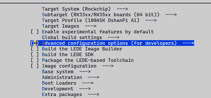
  1. First enable Advanced configuration options (for developers):

  1. Enable Target Options, and fill in the target optimization GCC build parameters:

Target optimization build parameter configuration

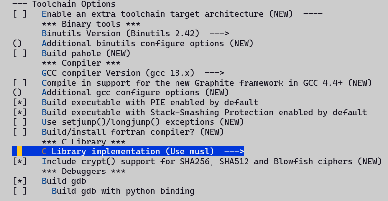
  1. Enable Toolchain Options, and configure the toolchain options:

Warning: The C library implementation here must be musl, otherwise after flashing and entering the system, all packages downloaded via Opkg will not be usable! (Because the default packages are all musl C library)!

Configure busybox Options

In some scenarios, OpenWrt's non-busybox configuration cannot cover the requirements and needs to be implemented through packages inside busybox. In this case, you need to customize the busybox options. You can refer to the following configuration method:

  1. Select Base System -> Customize busybox options

Among them, Settings are some additional parameter configurations, such as build options; Applets are configurations for command-line tools. We just need to make the corresponding configurations as needed.

Note that when OpenWrt's packages can provide the corresponding functionality, we should not provide it again in the busybox configuration. Otherwise, in the final stage of building, an error message will be prompted indicating that it is already provided but also exists in Busybox.

Configure Applications

OpenWrt contains a rich set of applications that can greatly enrich the router's functionality, including various libraries, command-line tools, and GUI apps (commonly referred to as plugins). Here we only provide some configuration examples for common apps.

Most packages are arranged in an orderly alphabetical order under each major category by classification. For example, if we want to enable sftp-server, we can find it under: Network -> SSH page, and then select it. An example is as follows:

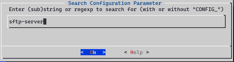
There is also a quicker method. Through the menuconfig configuration item search function, you can quickly locate the page to be configured and select it. Below is an example of the search method targeting sftp-server:

  1. In the menuconfig main interface, type / to enter the search page, and then enter sftp-server in the search page

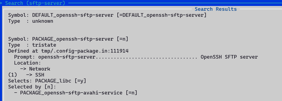
  1. According to the number index corresponding to (N) in the search result page, you can quickly jump to a certain result. For example, if there is only one result here, then the index is 1. Typing 1 directly will jump to the corresponding page.

  1. You can see that the package corresponding to the current search page is =n, not enabled; after typing the index value to jump over, it is indeed not enabled. Correspondingly, at this time we only need to type y to enable it.

  1. For cases with multiple search results, we can use the spacebar to turn pages and view results, or use the up and down keys to view results line by line. By viewing the detailed information on the search page, we can determine whether it is the package we are looking for.

Note: It is recommended to use both methods flexibly, which can greatly speed up development efficiency.

Configure kernel Options

The kernel configuration options are different from others. They are not configured by make menuconfig, but have a separate make target. An example is as follows:

make kernel_menuconfig

When the entire project has not been built before, executing the above command will automatically build the dependent toolchain first, which may be time-consuming. It is recommended to build the entire project once first, and then customize the kernel options.

Because the first time the entire project is built, all dependent source packages will be downloaded and the corresponding toolchain will be built, which is quite time-consuming.

Save Configuration

For the OP domain configuration, use the following command to generate the minimal configuration file:

./scripts/diffconfig.sh > defconfig

For the kernel domain configuration, when configuring the kernel, the configuration will be automatically updated to the config file under target, so there is no need to save it manually.

Build

Process

First perform the download operation, resolve any problems that may be encountered during the download process, and then execute the build process.

Avoiding downloads during the default build process is because if a certain package fails, when building again, it will check one by one whether the previous packages have been downloaded and built. This is not conducive to debugging. Execute the command as follows:

# When the download fails, use -j1 to view the specific failure information
# The downloaded source packages are all stored in the dl directory under the project root directory
make download -j$(nproc)

# The first build is recommended to use single thread, testing multi-thread builds may fail!
make V=s -j1

For the second build, you can execute:

make V=s -j$(nproc)

If you need to reconfigure, follow the process below:

rm -rf .config
make menuconfig
make V=s -j$(nproc)

Common Build Errors

Some programs will fail during building. At this time, we need to re-run using make V=s -j1 to better see the errors during the build process. Common ones include undefined or library-not-found errors, or errors caused by Werror. Below is a simple example of a solution.

For example, when initially using glibc for building, mbedtls and vlmcsd kept failing to build. Adding the following modifications allowed them to build:

diff --git a/package/libs/mbedtls/Makefile b/package/libs/mbedtls/Makefile
index 4e0a4a034..54a0b2d45 100644
--- a/package/libs/mbedtls/Makefile
+++ b/package/libs/mbedtls/Makefile
@@ -121,7 +121,7 @@ This package contains mbedtls helper programs for private key and
CSR generation (gen_key, cert_req)
endef

-TARGET_CFLAGS += -ffunction-sections -fdata-sections
+TARGET_CFLAGS += -ffunction-sections -fdata-sections -Wno-error=stringop-overflow
TARGET_CFLAGS := $(filter-out -O%,$(TARGET_CFLAGS))

CMAKE_OPTIONS +=
--- Makefile.orig       2025-11-14 01:58:43.376952312 +0800
+++ Makefile 2025-11-14 01:53:50.865983762 +0800
@@ -37,4 +37,6 @@
$(INSTALL_BIN) ./files/vlmcsd.ini $(1)/etc/vlmcsd/vlmcsd.ini
endef

+TARGET_LDFLAGS += -lresolv -lpthread
+
$(eval $(call BuildPackage,vlmcsd))

For more errors during the build process, flexibly use AI tools and search engines, and you can basically solve the problems encountered in building.

Flashing

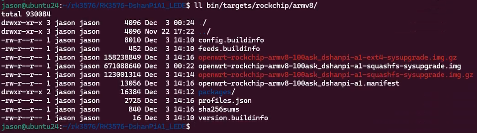
After the build is complete, two types of image packages will be generated in the corresponding bin/target/xxxx directory: one is ext4 and the other is squashfs. If you need to restore default configuration, you need to use the squashfs image package.

Note: After OpenWrt compilation is complete, the flashable image will be compressed into a zip format file. You need to perform the decompression operation first before it can be used as the flashing image for the flashing tool. An example is as follows:
jason@ubuntu24:~/LEDE/bin/targets/rockchip/armv8$ gunzip -k openwrt-rockchip-armv8-100ask_dshanpia1-squashfs-sysupgrade.img.gz -f
gzip: openwrt-rockchip-armv8-100ask_dshanpia1-squashfs-sysupgrade.img.gz: decompression OK, trailing garbage ignored

After decompressing to get the img image, refer to 《Board Introduction and Development Environment Setup - 4.3 Start Flashing》 for flashing.

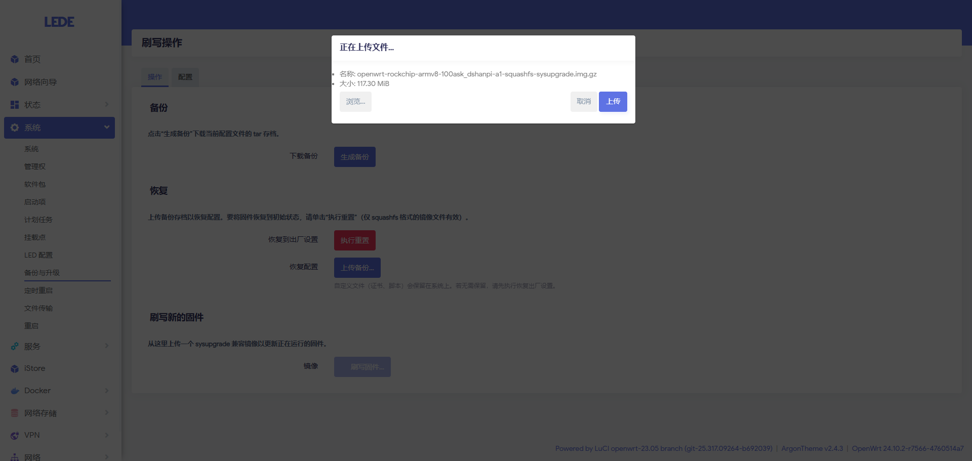
The OpenWrt system's built-in online flashing function has problems when used. Refer to the 《Existing Feature Optimization - 1.3 sysupgrade image cannot be used》 section for adaptation. After adaptation, you can directly flash via the web method. An example is as follows:

Note: The image package selected for web page online upgrade is the compressed image package!

OPENWRT System 1: A1 Board Introduction and Development Environment Setup

· 11 min read
Yuxuan
100askTeam yuxuan.
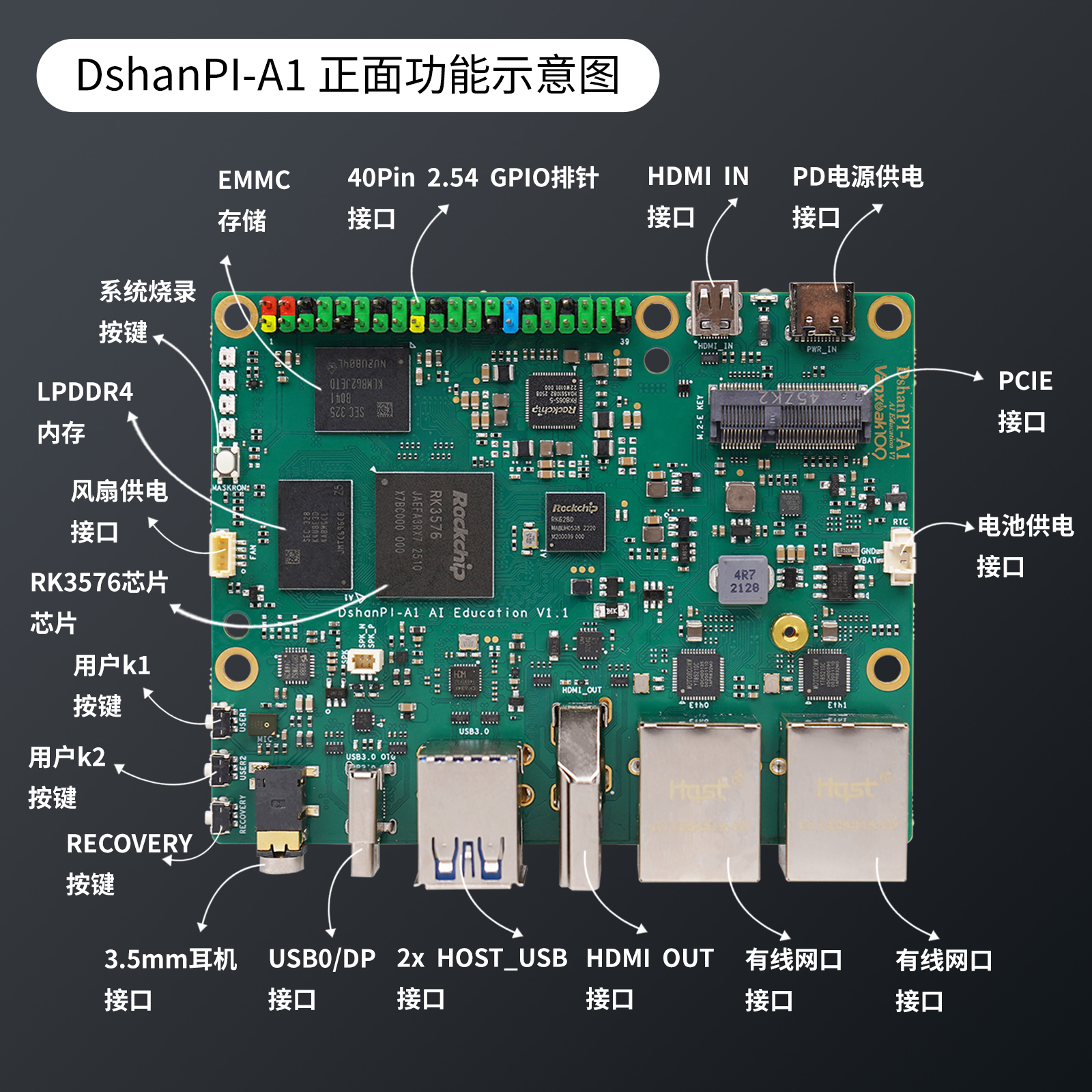
DShanPl-A1 Education is deeply optimized for artificial intelligence education and project development. Based on Rockchip's RK3576 processor, it integrates 4 Cortex-A72 and 4 Cortex-A53 cores with NEON instruction set support, supports 8K@30fps H.265, VP9 AVS2 and AV1 decoders, 4k@60fps H.264 decoder and 4K@60fps AV1 decoder; it also supports 4K@60fps H.264 and H.265 encoders. The built-in 3D GPU is fully compatible with OpenGl ES1.1/2.0/3.2, 0penCL2.0 and Vulkan 1.1. The embedded NPU computing power reaches up to 6TopS, supporting INT4/INT8/INT16/FP16 mixed operations.

The board has rich peripheral interfaces, and the onboard SOC delivers strong performance, providing a mid-to-high-end performance SBC (Single Board Computer) experience, smart router, etc. Below are some corresponding application scenario examples:

  • Smart standalone mini computer, with office, education, programming development, embedded development and other functions
  • Personal git repository, server, NAS, soft router, private cloud
  • Robot, drone and other projects
  • TV box, smart home hub, home security monitoring, smart speaker and other smart devices
OpenWrt is an open-source Linux-based embedded operating system, mainly used for network devices such as routers. Compared with traditional router firmware, OpenWrt is not a fixed-function firmware, but a freely extensible software platform. Users can install various components through the opkg package system to implement routing, firewall, VPN, NAS, intranet penetration and many other functions. It provides an SSH command line and LuCI Web interface, with flexible configuration, supporting advanced network features such as VLAN, IPv6, QoS, and multi-WAN. OpenWrt has a clear, modular structure, with the core including the UCI configuration system, netifd network management, dnsmasq, hostapd, and the firewall framework. With its high customizability and strong community support, OpenWrt is suitable for home and enterprise networks as well as secondary development, making it an ideal choice for building high-function routers and network application platforms. Lean's OpenWrt LEDE repository is an open-source project maintained by Lean, aimed at providing stable, efficient and feature-rich support for the OpenWrt system. As a combination of the OpenWrt and LEDE projects, the Lean version provides optimized firmware and enhanced features for a wide range of routers and embedded devices, and is widely used in home, enterprise and laboratory environments. The Lean repository contains numerous patches, optimizations, drivers, and various third-party applications from the global open-source community, greatly enhancing the customizability and performance of the OpenWrt system.

The goal of this project is to build a lightweight NAS (lightweight NAS) application based on the DShanPl-A1 Education single-board. The best implementation path is to adopt the mature and highly extensible open-source routing system OpenWrt LEDE. With OpenWrt's complete Linux environment and rich ecological plugins, we can install storage services, network services, intranet penetration, secure access and other functional modules in the system as needed. Through the collaborative configuration among these plugins, combined with OpenWrt's powerful network management capabilities, a lightweight NAS solution based on a soft router architecture can be built.

Development Environment

Environment Description

The official OpenWrt build recommends using the native GNU/Linux environment, but it also supports building using Windows WSL mode. Using a WSL development environment on Windows eliminates the need to configure a virtual machine environment, and can also be used in environments where installing VMware is restricted. Therefore, the author's build and development environment mostly prioritizes using WSL.

WSL (Windows Subsystem for Linux) provides a native-level Linux environment on Windows, suitable for developers to carry out cross-platform or Linux-related project development. Its main advantages include:

  1. Lightweight and fast: No virtual machine or dual system is needed. Startup and running are almost as fast as native Linux, with low resource consumption.
  2. Seamless integration with Windows: Can directly access the Windows file system, and use Windows tools (such as VSCode, browser) together with Linux tools.
  3. Native Linux experience: Supports most Linux commands, package managers, and build tools. You can directly compile, debug, and run services.
  4. Easy to install and maintain: One-click installation from the Microsoft Store. System updates and environment switching are very convenient.
  5. Excellent development experience: Supports mainstream development environments such as Docker (WSL2), Git, Python, Node.js, C/C++, suitable for embedded, server, network, AI and other fields.
  6. Good cross-platform compatibility: Can build Linux-runnable software on Windows, such as compiling OpenWrt, building drivers, generating cross-compiled packages, etc.
Overall, WSL allows developers to obtain near-native Linux capabilities on Windows at minimal cost, greatly improving efficiency and flexibility. We use VSCode remote access, which makes it very convenient to complete development work. Below are some WSL environment configurations that need to be set before building. Copy this part to

Environment Variable Configuration

Refer to the official documentation: Build system setup WSL

In the WSL environment, in the build user's .bashrc, add the corresponding configuration information according to the instructions below to solve the problem that Windows environment variables are also effective by default in WSL. After this setting, the environment is basically consistent with the native GNU/LINUX environment, and there will be no issues with WSL's import mechanism.

# GO build configuration, if it cannot be built, open this
#export GO111MODULE=on
#export GOPROXY=https://goproxy.cn

# proxy, replace this with the proxy service IP:PORT of your own Windows environment
export http_proxy=http://192.168.31.50:6080
export https_proxy=http://192.168.31.50:6080

export REPO_URL='https://mirrors.tuna.tsinghua.edu.cn/git/git-repo'

# Filter Windows PATH stuff
export PATH=$(echo $PATH | sed -e 's|:[^:]*WindowsApps[^:]*||g')
export PATH=$(echo $PATH | tr ':' '\n' | grep -v NVIDIA | tr '\n' ':')
export PATH=$(echo $PATH | tr ':' '\n' | grep -v 'Files' | paste -sd ':' -)
export PATH=$(echo $PATH | tr ':' '\n' | grep -v 'VS' | paste -sd ':' -)
export PATH=$(echo $PATH | tr ':' '\n' | grep -v '/mnt/' | paste -sd ':' -)

WSL Network Proxy Settings

Since some tool packages are on GitHub, default network downloads may often fail. We can choose to run the corresponding proxy software on Windows, then enable allowing other devices to connect, and then configure the corresponding http_proxy and https_proxy environment variables in WSL, which can conveniently accelerate GitHub access.

Below are some configuration examples:

  1. Proxy software enables LAN device connection

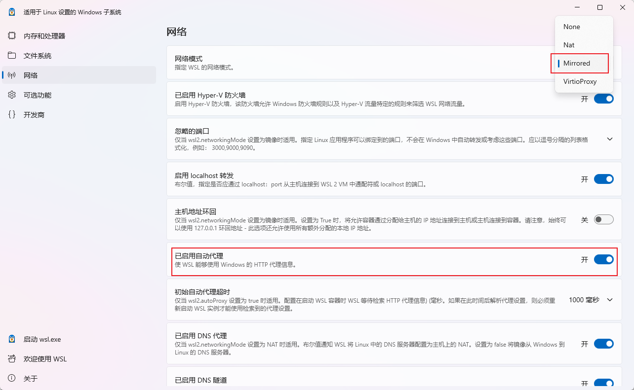
  1. Set the network mode to Mirrored in WSL Settings

For more details, please refer to Microsoft's official documentation: Access network applications with WSL - Mirrored mode networking

  1. After configuration, first run wsl --shutdown, and then restart wsl ubuntu
  2. Check whether the environment variable WSL_PAC_URL has been configured successfully. A successful example is as follows:

  1. Configure terminal http and https proxies, with automatic PAC filtering
export http_proxy=$WSL_PAC_URL
export https_proxy=$WSL_PAC_URL

Tips: You can directly write this into the current user's .bashrc, so you don't have to execute the proxy settings every time.

Flashing Test Method

This section introduces the basic method of flashing the LEDE image. You need to master the method of flashing the image in advance. Below is a detailed step-by-step introduction.

Hardware Connection

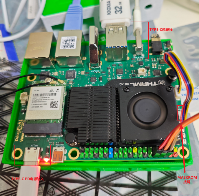
To flash the system image, in addition to the dshanpi-a1 board, you also need to prepare TypeC USB cable, 30W PD power adapter (recommended to purchase from Weidongshan store), as shown below:

Install Driver and Flashing Software

The tool packages and image files that need to be downloaded are as follows:

Find the driver installation tool package DriverAssitant_v5.1.1.zip in the previously downloaded materials, extract it, then open and launch the download program DriverInstall.exe, click driver installation, as follows:

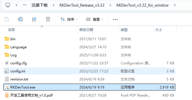
Extract the flashing tool RKDevTool_Release_v3.32.zip downloaded from the previous link, and then directly double-click RKDevTool.exe.

Start Flashing

After the preparation is complete, follow the steps below to make the device enter the MASKROM flashing mode:

1. Connect the usb2.0/3.0 otg cable (i.e., the type-c flashing data cable, the other end of the data cable connects to the computer's USB2.0/3.0 blue port);

2. Press and hold the **<font style={{color: 'rgb(28, 30, 33)', backgroundColor: 'rgb(246, 247, 248)'}}>MASKROM</font>** button, do not release it first ;

3. Then connect the power supply, and the dshanpi-a1 will enter the **<font style={{color: 'rgb(28, 30, 33)', backgroundColor: 'rgb(246, 247, 248)'}}>MASKROM</font>** flashing mode;

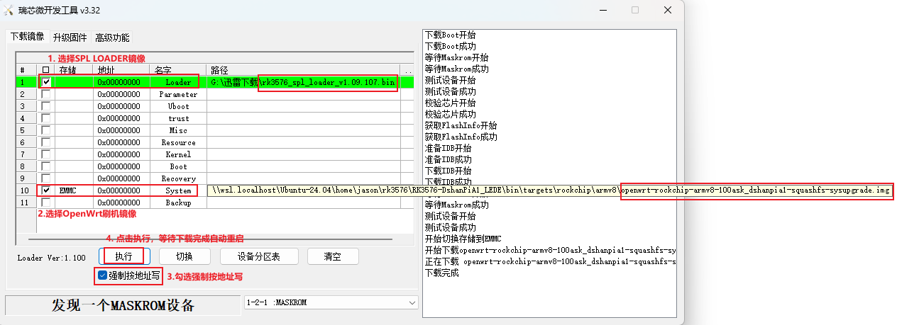
Open the flashing tool, select the interface parameters as below, configure the flashing image and parameters, then click execute, and wait for the download to complete. After flashing is complete, the board will automatically restart, and then the LEDE pixel LOGO will appear, indicating that flashing is complete.

OpenWrt EMMC flashing parameter configuration example

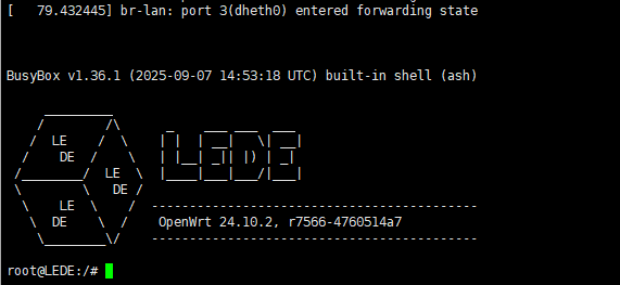
System boot shell prompt

Note: After OpenWrt compilation is complete, the flashable image will be compressed into a zip format file. You need to perform the decompression operation first before it can be used as the flashing image for the flashing tool. An example is as follows:
jason@ubuntu24:~/LEDE/bin/targets/rockchip/armv8$ gunzip -k openwrt-rockchip-armv8-100ask_dshanpia1-squashfs-sysupgrade.img.gz -f
gzip: openwrt-rockchip-armv8-100ask_dshanpia1-squashfs-sysupgrade.img.gz: decompression OK, trailing garbage ignored

# Wait for the img image file input
jason@ubuntu24:~/LEDE/bin/targets/rockchip/armv8$ ls -lh openwrt-rockchip-armv8-100ask_dshanpia1-squashfs-sysupgrade.img
-rw-r--r-- 1 jason jason 640M Nov 28 02:24 openwrt-rockchip-armv8-100ask_dshanpia1-squashfs-sysupgrade.img

Reference Documents

DshanPI-A1 Audio Recording, Playback and Noise Analysis

· 14 min read
Yuxuan
100askTeam yuxuan.

Audio Playback

Speaker Device

Let's first look at how to use this speaker. First, list the audio playback devices.

aplay -l
**** List of PLAYBACK Hardware Devices ****
card 0: rockchipes8388 [rockchip-es8388], device 0: dailink-multicodecs ES8323 HiFi-0 [dailink-multicodecs ES8323 HiFi-0]
Subdevices: 1/1
Subdevice #0: subdevice #0
card 1: rockchiphdmiin [rockchip,hdmiin], device 0: 2a640000.sai-dummy_codec dummy_codec-0 [2a640000.sai-dummy_codec dummy_codec-0]
Subdevices: 1/1
Subdevice #0: subdevice #0
card 2: rockchipdp0 [rockchip-dp0], device 0: rockchip-dp0 spdif-hifi-0 [rockchip-dp0 spdif-hifi-0]
Subdevices: 1/1
Subdevice #0: subdevice #0
card 3: rockchiphdmi [rockchip-hdmi], device 0: rockchip-hdmi i2s-hifi-0 [rockchip-hdmi i2s-hifi-0]
Subdevices: 1/1
Subdevice #0: subdevice #0

It can be seen that a total of 4 audio cards are detected (card 0 ~ card 3)

  • Play audio to speaker/headphones: use card 0, device 0
  • HDMI audio output: use card 3, device 0
  • DisplayPort audio: use card 2, device 0
  • Capture HDMI input audio: use card 1, device 0

The speaker is card0: subdevice#0, and the corresponding ALSA device is hw:0,0

**** List of PLAYBACK Hardware Devices ****
card 0: rockchipes8388 [rockchip-es8388], device 0: dailink-multicodecs ES8323 HiFi-0 [dailink-multicodecs ES8323 HiFi-0]
Subdevices: 1/1
Subdevice #0: subdevice #0

Create and Play a Simple Test Tone

# Create a 1kHz sine wave WAV file at 8kHz sample rate (5 seconds)
ffmpeg -f lavfi -i "sine=frequency=1000:duration=5" -c:a pcm_s16le -ar 8000 test_tone.wav
# Play the file
aplay test_tone.wav
Playing WAVE 'test_tone.wav' : Signed 16 bit Little Endian, Rate 8000 Hz, Mono

The test commands all succeeded, but no sound was heard. We need to check the properties of this speaker. It is very likely an audio routing issue. First, we need to determine the troubleshooting approach:

The audio chip (ES8388) is designed with:

  • Software control layer: Speaker Switch - controls whether the audio stream is sent to the chip
  • Hardware control layer: OUT1/OUT2 Switch - controls the chip's physical pin output

Audio Playback Debugging

First, open the audio visualization tool to take a look.

alsamixer -c 0

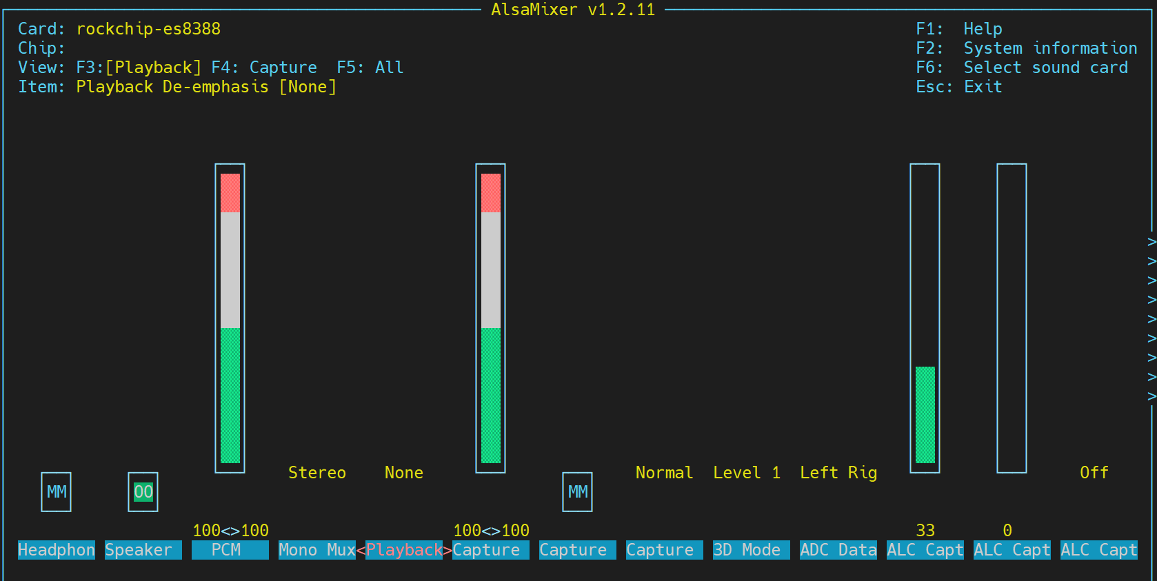
image-20251205094259863

It can be seen that the playback status is abnormal: MM 00. We need to further confirm which configuration is the problem. Use the PulseAudio control tool.

pactl list short sinks
0 alsa_output.0.HiFi__hw_rockchipes8388__sink module-alsa-card.c s16le 2ch 44100Hz SUSPENDED
1 alsa_output.1.stereo-fallback module-alsa-card.c s16le 2ch 44100Hz SUSPENDED

Some explanations:

  • Sink: the endpoint of audio output
  • PulseAudio architecture
Application -> Audio stream -> PulseAudio server -> Sink -> Hardware
(player) (mixer) (output device) (sound card)

Status description

  • RUNNING: audio is playing
  • IDLE: idle, ready
  • SUSPENDED: suspended, power-saving mode
  • UNLINKED: not connected

Device details

  • sink 0: alsa_output.0.HiFi__hw_rockchipes8388__sink
    • Corresponds to ALSA sound card 0 (ES8388 audio chip)
    • High fidelity (HiFi) output
  • sink 1: alsa_output.1.stereo-fallback
    • Fallback/backup output device
    • Used when the primary device is unavailable

Both audio sinks are in SUSPENDED state

0 ... SUSPENDED
1 ... SUSPENDED

SUSPENDED state means:

  • PulseAudio thinks there is no audio stream to play
  • To save power, it automatically suspends audio output
  • The system is ready to receive audio, but there is currently no active audio stream

Root cause chain:

  1. At system startup -> PulseAudio loads audio devices

  2. No active audio stream -> PulseAudio suspends the device (SUSPENDED)

  3. Hardware routing not activated -> OUT1/OUT2 switches are off by default

  4. When starting to play audio:

    • PulseAudio wakes up the device
    • But the hardware switches (OUT/OUT2) are still off
    • Need to manually amixer -c 0 sset 'OUT1' on

    After my testing, after turning on

    amixer -c 0 sset 'OUT2' on

    the speaker audio can be played normally. Here as a record, I list some useful commands I used during debugging.

    #1. View more detailed sink information
    pactl list sinks
    Sink #0
    ...
    Sink #1
    ...
    # 2. View current audio streams
    pactl list sink-inputs
    #3. ALSA content control
    amixer -c 0 scontents
    ...
    amixer -c 0 get 'Speaker'
    amixer -c 0 get 'Master'
    amixer -c 0 get 'Headphone'

There are multiple solutions to this problem, listed below.

Solution 1: Prevent auto-suspend

# Edit PulseAudio configuration
vi /etc/pulse/default.pa
# Prevent auto-suspend
load-module module-suspend-on-idle timeout=0 # 0 means never suspend
# Increase timeout
load-module module-suspend-on-idle timeout=3600 # 1 hour
# Restart PulseAudio
pulseaudio -k
pulseaudio --start

Solution 2: Automatically activate hardware at startup

# Create startup script /etc/pulse/audio-init.sh
#!/bin/bash
# Wait for PulseAudio to start
sleep 3
# Activate hardware output
amixer -c 0 sset 'OUT2' on
amixer -c 0 sset 'Speaker' on
# Set appropriate volume
amixer -c 0 sset 'Output 2' 90%

Solution 3: Use udev rules

# Create /etc/udev/rules.d/90-audio.rules
ACTION=="add", SUBSYSTEM=="sound", KERNEL=="card0", \
RUN+="/usr/bin/amixer -c 0 sset 'OUT2' on"
# Takes effect after reboot

Solution 4: Simplest temporary test

# Activate the device before playing
amixer -c 0 sset 'Speaker' on
amixer -c 0 sset 'OUT2' on
amixer -c 0 sset 'Output 2' 90%
# You can also permanently save settings (did not take effect)
alsactl store

Summary: The problem is actually:

  • Software layer: PulseAudio is normal
  • Driver layer: ALSA correctly identifies the device
  • Hardware layer: OUT2 physical switch needs to be manually activated

tips: Audio routing

# Assume there are multiple audio devices:
# 0 - built-in speaker
# 1 - USB headset
# 2 - HDMI output

# Send Chrome audio to the headset
pactl move-sink-input $(pactl list short sink-inputs | grep chrome | awk '{print $1}') 1
# Send music player to HDMI
pactl move-sink-input $(pactl list short sink-inputs | grep spotify | awk '{print $1}') 2

Audio Recording

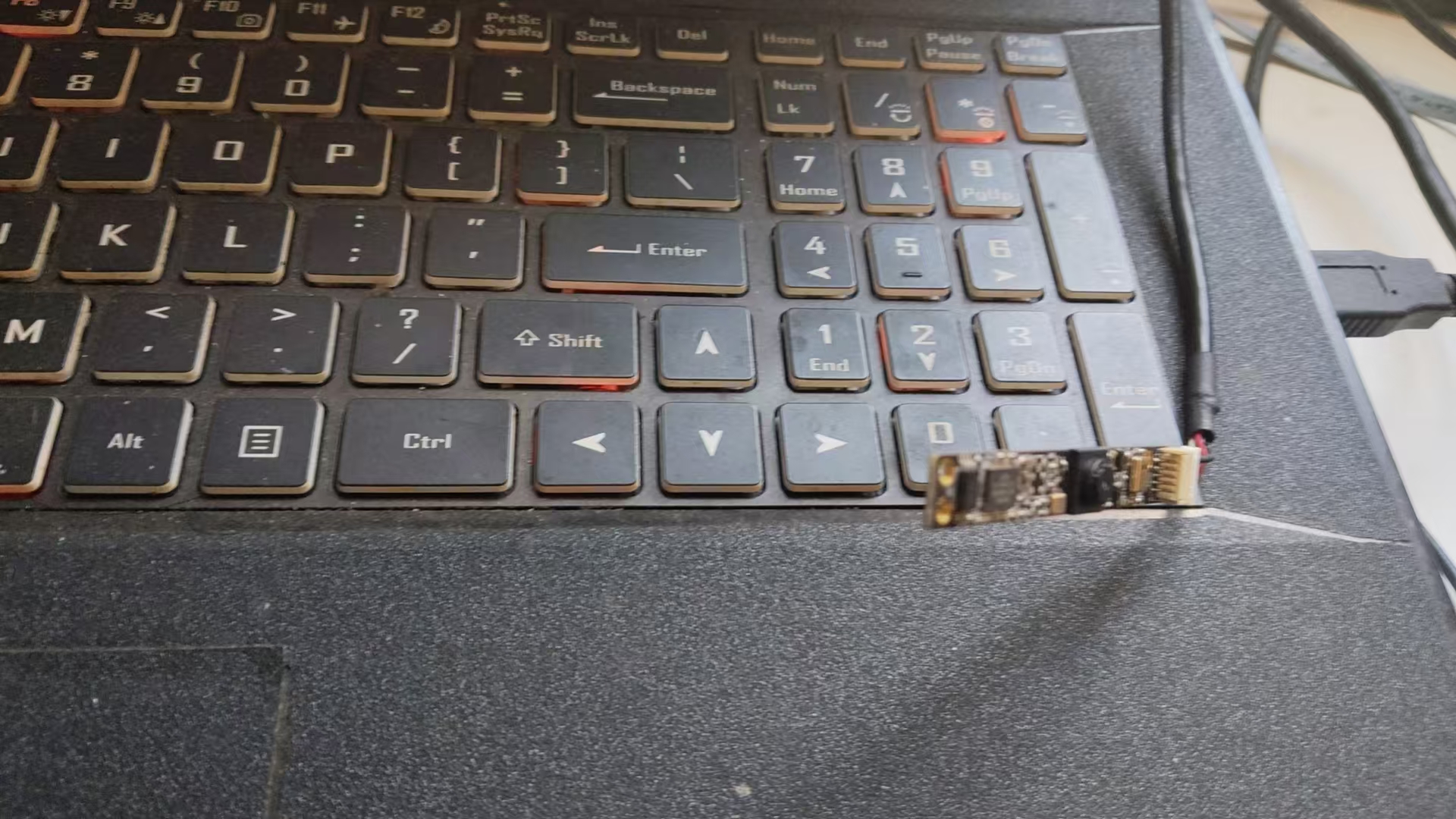
The hardware used is the 100ask 200w USB camera + audio MEMS integrated module, as shown in the figure below.

7de0c186abbafe3783a045089397308b

Device Information Acquisition

First, we need to obtain the information of the entire MEMS. It communicates with RK3576 via USB. There are several ways to see its information.

v4l2-sysfs-path
Video device: video36
video: video37
sound card: hw:4
pcm capture: hw:4,0
mixer: hw:4
Video device: video37
sound card: hw:4
pcm capture: hw:4,0
mixer: hw:4
.....
alsactl info
......
- card: 4
id: Camera
name: USB 2.0 Camera
longname: lihappe8 Corp. USB 2.0 Camera at usb-xhci-hcd.8.auto-1.2.2, high speed
driver_name: USB-Audio
mixer_name: USB Mixer
components: USB038f:0541
controls_count: 4
pcm:
- stream: CAPTURE
devices:
- device: 0
id: USB Audio
name: USB Audio
subdevices:
- subdevice: 0
name: subdevice #0
.....

It can be seen that the name of this device in ALSA is hw:4,0

Audio Recording Test

# Record a segment of background noise
arecord -D hw:4,0 -f S16_LE -r 8000 -c 2 -d 10 noise
Recording WAVE 'noise.wav' : Signed 16 bit Little Endian, Rate 8000 Hz, Stereo
aplay noise.wav
Playing WAVE 'noise.wav' : Signed 16 bit Little Endian, Rate 8000 Hz, Stereo

A clear "squeak" sound can be heard. The self-noise of this MEMS is still quite large. Noise reduction is needed later before normal voice communication can be performed.

Noise Analysis

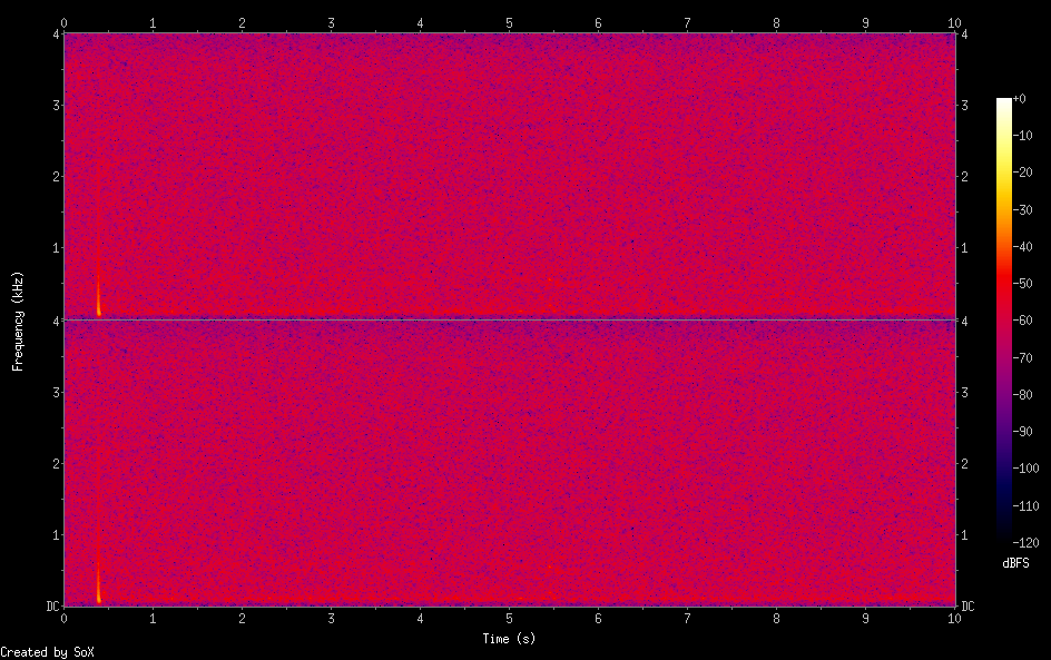
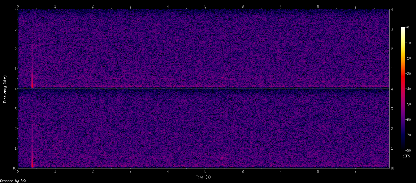
Use sox to generate a spectrogram.

sox noise.wav -n spectrogram -o noise_spectrogram.pn

noise_spectrogram

# Global spectrum
sox noise.wav -n spectrogram -d 10 -x 1200 -z 80 -o noise_full.png

noise_full

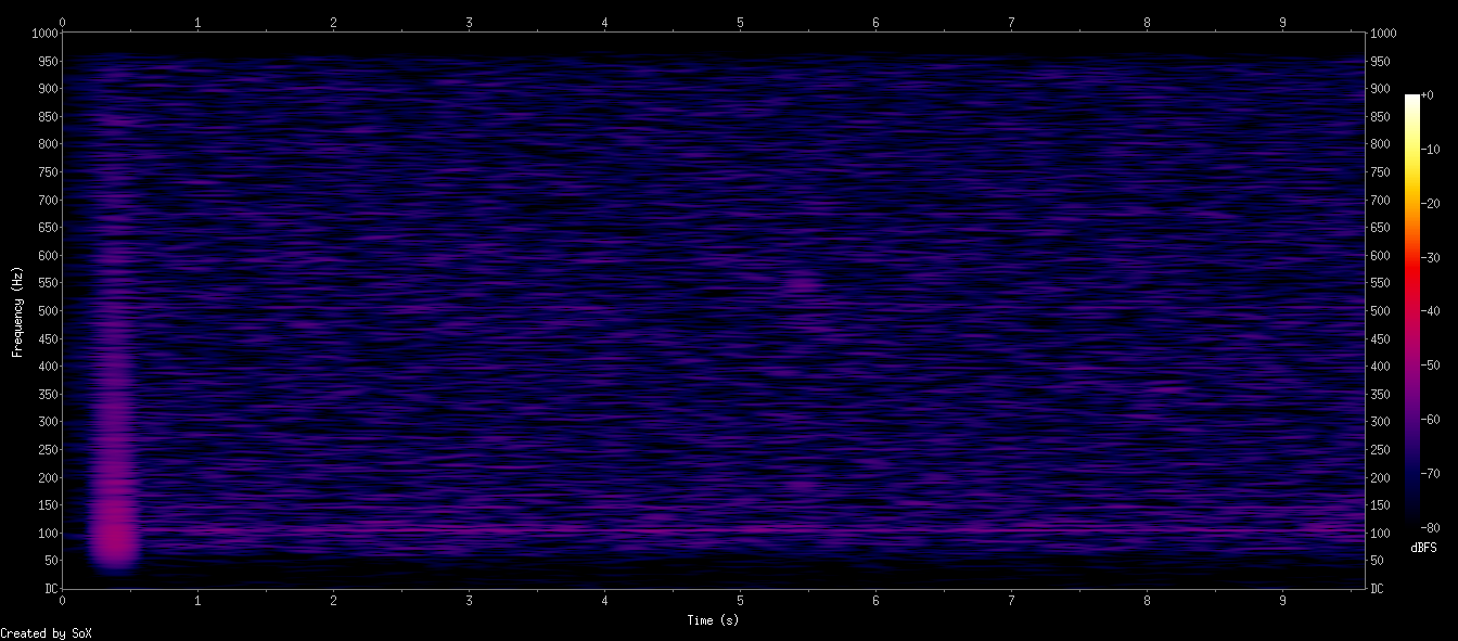
sox noise.wav -r 2000 -c 1 noise_2k.wav
sox noise_2k.wav -n spectrogram -d 10 -x 1200 -z 80 -o noise_low.png

noise_low

Overall observation: the background noise is "approximately white noise + strong low-frequency peaks + slight mid-frequency texture noise"

1. There is a very obvious low-frequency energy blob around 0~200Hz (especially <100Hz)

This generally means:

  • Mechanical/power-related noise
  • Fan, vibration, chassis resonance
  • Power ripple (50Hz / 60Hz + fundamental)
  • Microphone directivity/enclosure coupling amplifying ultra-low frequency noise

2. The 1kHz~4kHz range is random noise (approximately white noise) with low energy

This indicates the microphone self-noise is typical:

  • MEMS microphone inherent noise
  • ADC self-noise
  • Amplifier input noise

This part is the system noise floor.

3. High frequency (>6kHz) has no strange peaks at all

This is very good -> no obvious:

  • Digital EMI
  • Clock leakage
  • Sampling jitter noise

4. No obvious "howling mode" appears

None of the three figures show typical howling characteristics:

  • Howling is usually a fixed-frequency bright line that remains unchanged
  • The figures only show a pulse at the starting moment (may be the click sound when recording starts)

No stable peak persists over time.

Per-figure analysis


(A) First figure: Full spectrum (up to 4kHz)

The characteristics look like:

Overall reddish/purple, noise density is high but uniform Obvious vertical line around 50Hz 100Hz, 150Hz also have slight energy

-> This is almost certainly:

Power frequency noise (50/60Hz) + harmonics (100/150Hz)

Reasons:

  • USB power supply brings a lot of 50/60Hz hum
  • Poor isolation of the sound card or microphone analog front-end
  • Unclean ground (such as USB common ground loop)

(B) Second figure: Version with narrowed dynamic range (-80dBFS)

This figure additionally exposes:

There is a very narrow horizontal line at 1.8kHz ~ 2.2kHz

Very faint, but stably present.

This indicates:

System clock/PLL interference leakage

Common in:

  • I2S/MCLK leakage
  • Clock coupling of the microphone on the PCB
  • Digital power noise superimposed on the microphone analog part

This part will not cause howling, but will reduce SNR.


(C) Third figure: Low frequency to 1000Hz

Very typical:

The noise in the <150Hz region is much higher than other frequency bands

Like a large "bulb" shape, very obvious.

This indicates:

Low-frequency vibration + power noise are the main noise floor sources

Including:

  • Chassis vibration, fan, tabletop resonance
  • Power 50/60Hz + harmonics
  • The microphone's own LF roll-off is insufficient

Comprehensive judgment: Background noise composition ratio

Noise typeRatioFeature
Low-frequency mechanical/power noise (<200Hz)50%Largest source, from power, chassis, vibration
Power frequency leakage 50/60Hz + harmonics25%Strongest fixed peak in the figure
Microphone inherent white noise20%Random noise scattered in 1k~4kHz
Digital clock leakage (around 2kHz)5%A very weak but visible thin line

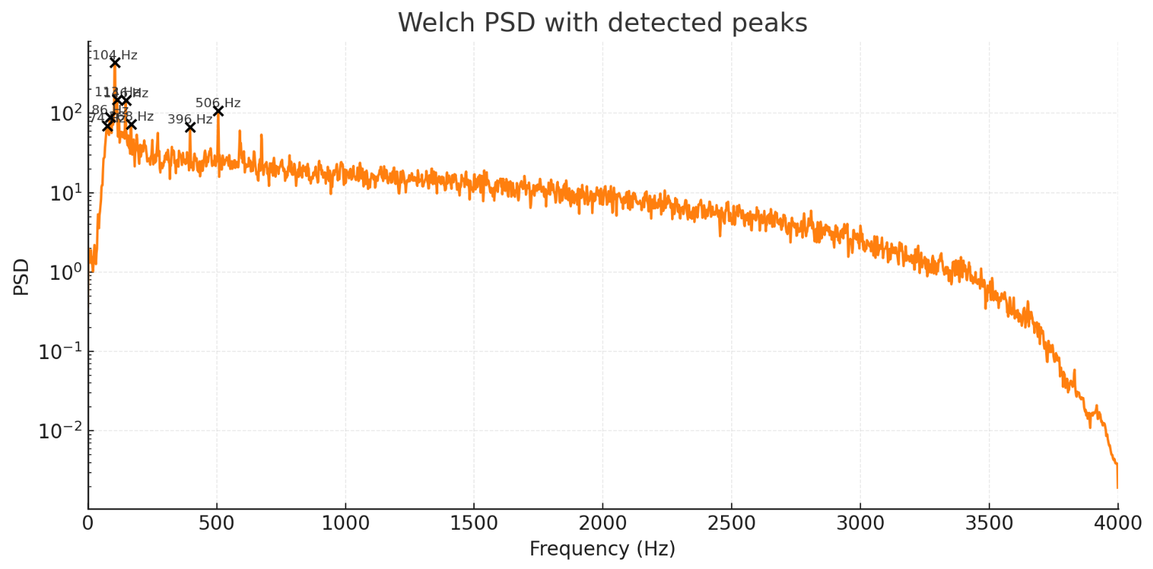
PSD Noise Model Analysis

Use Python to generate a PSD noise model.

import numpy as np
import matplotlib.pyplot as plt
from scipy.io import wavfile
from scipy.signal import welch, find_peaks, spectrogram, butter, sosfilt
import IPython.display as ipd
import os

rate, data = wavfile.read("/mnt/data/noise.wav")
if data.ndim>1:
data = data.mean(axis=1)
data = data.astype(np.float32)
N = len(data)
duration = N / rate

# Calculate overall RMS and dBFS
# Assuming 16-bit PCM if dtype was int16; determine scale
# infer max possible value from original dtype by reloading header:
import struct
# Determine dtype max
# but we'll normalize by max of int16 if dtype came as int16, else use max(abs(data))
max_possible = 32768.0
rms = np.sqrt(np.mean(data**2))
dbfs_rms = 20*np.log10(rms / max_possible) if rms>0 else -np.inf

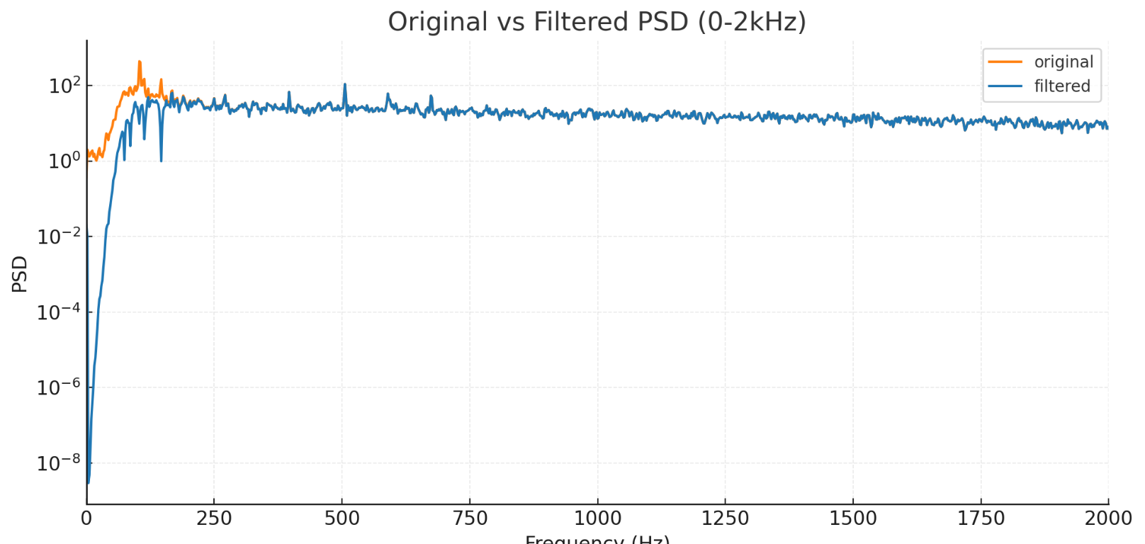
# Welch PSD
f, Pxx = welch(data, fs=rate, nperseg=4096, scaling='density')
# find peaks in PSD (in linear)
peaks, props = find_peaks(Pxx, height=np.max(Pxx)*0.15, distance=5)
peak_freqs = f[peaks]
peak_heights = props['peak_heights']

# Find dominant low-frequency peak under 500Hz
low_idx = np.where(f<=500)[0]
low_f = f[low_idx]
low_P = Pxx[low_idx]
lp_peaks, lp_props = find_peaks(low_P, height=np.max(low_P)*0.2)
lp_freqs = low_f[lp_peaks]
lp_heights = lp_props['peak_heights']

# Short-time energy to find transient (e.g., first second pulse)
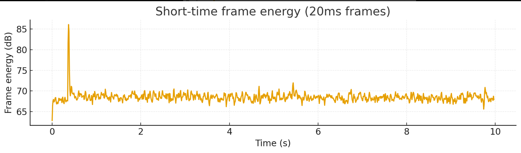
frame_ms = 20
frame_len = int(rate * frame_ms/1000)
hop = frame_len//2
frames = []
for start in range(0, N-frame_len, hop):
frames.append(np.sum(data[start:start+frame_len]**2))
frames = np.array(frames)
frame_times = (np.arange(len(frames))*hop)/rate

# detect where energy spikes relative to median
median_e = np.median(frames)
spikes = np.where(frames > median_e*8)[0] # 8x median
spike_times = frame_times[spikes]

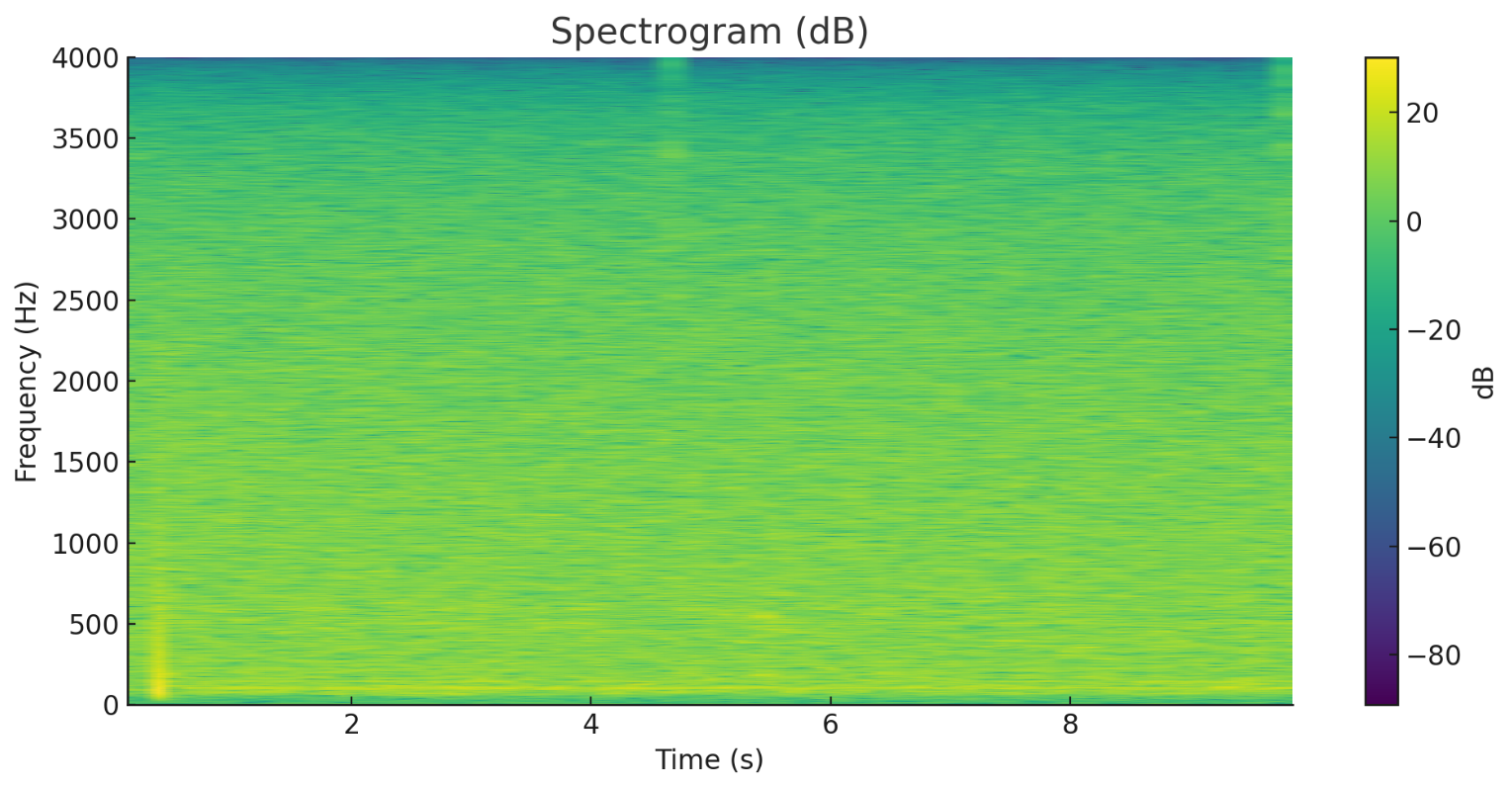
# Spectrogram
f_s, t_s, Sxx = spectrogram(data, fs=rate, nperseg=2048, noverlap=1024, scaling='density', mode='magnitude')

# Plot PSD with peaks marked
plt.figure(figsize=(10,5))
plt.semilogy(f, Pxx, color='tab:orange')
plt.scatter(peak_freqs, peak_heights, color='k', zorder=5)
for pf, ph in zip(peak_freqs, peak_heights):
plt.text(pf, ph*1.1, f"{pf:.0f} Hz", fontsize=8, ha='center')
plt.xlim(0, rate/2)
plt.xlabel("Frequency (Hz)")
plt.ylabel("PSD")
plt.title("Welch PSD with detected peaks")
plt.grid(alpha=0.3)
plt.tight_layout()
plt.savefig("/mnt/data/psd_peaks.png")

# Plot spectrogram (dB)
Sxx_db = 20*np.log10(Sxx + 1e-12)
plt.figure(figsize=(10,5))
plt.pcolormesh(t_s, f_s, Sxx_db, shading='gouraud')
plt.colorbar(label='dB')
plt.ylim(0, 4000)
plt.xlabel("Time (s)")
plt.ylabel("Frequency (Hz)")
plt.title("Spectrogram (dB)")
plt.tight_layout()
plt.savefig("/mnt/data/spectrogram_db.png")

# Prepare summary
summary = {
"sampling_rate": rate,
"duration_s": duration,
"rms": float(rms),
"dbfs_rms": float(dbfs_rms),
"dominant_peaks_hz": [float(p) for p in peak_freqs[:8]],
"dominant_peaks_vals": [float(p) for p in peak_heights[:8]],
"low_freq_peaks_hz": [float(p) for p in lp_freqs],
"low_freq_peaks_vals": [float(p) for p in lp_heights],
"spike_times_s": [float(s) for s in spike_times[:10]],
"spectrogram_image": "/mnt/data/spectrogram_db.png",
"psd_image": "/mnt/data/psd_peaks.png"
}

import json
with open("/mnt/data/noise_analysis_summary.json","w") as f:
json.dump(summary, f, indent=2)

# Display small tables and figures
from caas_jupyter_tools import display_dataframe_to_user
import pandas as pd

df_peaks = pd.DataFrame({
"freq_hz": peak_freqs,
"psd_val": peak_heights
})
display_dataframe_to_user("Detected PSD Peaks", df_peaks.head(20))

plt.figure(figsize=(10,3))
plt.plot(frame_times, 10*np.log10(frames+1e-12))
plt.xlabel("Time (s)")
plt.ylabel("Frame energy (dB)")
plt.title("Short-time frame energy (20ms frames)")
plt.grid(alpha=0.3)
plt.tight_layout()
plt.savefig("/mnt/data/frame_energy.png")
plt.show()

# Show audio player
ipd.display(ipd.Audio("/mnt/data/noise.wav"))

summary

image-20251205153910716

image-20251205153954232

image-20251205154029359

image-20251205154110367

Key quantitative results obtained:

  • Sample rate: 8000 Hz
  • Duration: 10.0 s
  • Overall RMS = 223.11 (samples), converted to -43.34 dBFS (normalized to 16-bit full scale 32768): indicates the noise floor is moderately high.
  • Detected significant frequency peaks (Welch PSD peak, in order of intensity, listing the first few):
    • approximately 74.2 Hz, 85.94 Hz, 103.52 Hz, 113.28 Hz, 146.48 Hz, 167.97 Hz, and smaller 396 Hz, etc.
  • Main peaks in the low-frequency band (≤500 Hz): 85.94, 95.70, 103.52, 113.28, 146.48 Hz - multiple near-frequency peaks, like a collection of power frequency/switching power supply harmonics or mechanical resonances.
  • Transient energy peaks (short-time energy frames, 20 ms) detected at: approximately 0.36-0.38 s there are several short pulses (may be startup click/human touch/transient events).

Conclusion: The noise consists of obvious low-frequency "hum/ripple/vibration" + broadband white noise (mid-to-high frequency), with low frequency being the main energy location.

Noise Reduction Scheme

1. Add a 2nd-order high-pass filter (fc = 80 Hz) to the audio chain

  • Directly remove most of the mechanical/power low-frequency without damaging the voice bandwidth (voice is mainly >100Hz).
  • Implementation: use the butter/sos in the DSP library or implement biquad yourself (Direct Form I or II).

2 Targeted notch filter

  • If there are still a few extremely narrow strong peaks after HPF (such as 103Hz), add one or two notches with Q=20~40. The higher the Q, the narrower the bandwidth, and the less it damages adjacent frequency bands, but the coefficients are closer to 1.
  • Consider real-time requirements: need to cascade hp -> notch(strong peak 1) -> notch(strong peak 2).

3 The essence is still hardware

  • Replace or improve the analog power supply (low-noise LDO, more bypass capacitors, star ground) or use a digital MEMS microphone with better SNR.
  • On embedded boards, keep switching power supply traces as far away from microphone differential/analog lines as possible.

Considerations for real-time audio quality

  • If very low latency is required (e.g., echo cancellation / real-time loopback), use IIR (biquad) one-way real-time implementation (extremely low latency), but note that the phase will change. If phase change is not allowed (e.g., for more accurate positioning), using FIR + zero-phase will have a latency cost.

Reference Filter Coefficients

Note: The coefficients given below are in the standard second-order section (biquad) format, arranged as [b0, b1, b2, a0, a1, a2] (a0 has been normalized to 1 or needs to be normalized when given). When implementing, usually normalize a0 to 1, and then implement according to Direct Form I/II.

High-pass: 2nd-order Butterworth (fc = 80 Hz, fs = 8000 Hz)

sos_hp first section coefficients (a0 normalized to 1):

b0 = 0.9565432255568767
b1 = -1.9130864511137533
b2 = 0.9565432255568767
a0 = 1.0
a1 = -1.911197067426073
a2 = 0.9149758348014336

Several notch filters (notch, Q=30)

(Three examples, taken from detected peak positions) Format is the same as above (b0,b1,b2,a0,a1,a2), a0 has been normalized to 1 in the output below:

  • notch @ 103.515625 Hz
b0 = 0.998648305437691
b1 = -1.99069933085876
b2 = 0.998648305437691
a0 = 1.0
a1 = -1.99069933085876
a2 = 0.9972966108753819
  • notch @ 146.484375 Hz
b0 = 0.9980904047539934
b1 = -1.9829844796660758
b2 = 0.9980904047539934
a0 = 1.0
a1 = -1.9829844796660758
a2 = 0.9961808095079867
  • notch @ 74.21875 Hz
b0 = 0.9990299707952924
b1 = -1.9946663265604048
b2 = 0.9990299707952924
a0 = 1.0
a1 = -1.9946663265604048
a2 = 0.9980599415905849

This noise analysis is the necessary material for traditional spectral subtraction audio filtering. Using the standard rnnoise AI noise reduction does not require it, but if you improve rnnoise yourself and do model fine-tuning, you need to refer to it to achieve better noise reduction results.

DshanPI-A1 Review Part 5: NPU in Action - YOLOv5 Real-Time Object Detection Acceleration

· 18 min read
Yuxuan
100askTeam yuxuan.

Preface

In previous articles we implemented CPU-based MediaPipe gesture recognition. Although it runs, the 15-25 FPS performance is still a bit strained, and CPU usage is high. This time I will squeeze the full hardware potential of the RK3576 - using the onboard NPU (Neural Processing Unit) to accelerate deep-learning inference. First, let's cover a few concepts.

What is an NPU? An NPU (Neural Processing Unit) is a hardware accelerator designed specifically for AI operations. Unlike a CPU/GPU, an NPU is deeply optimized for the matrix operations, convolutions, and other operations used in neural networks. The RK3576 chip has a built-in dual-core NPU with a theoretical compute capacity of 6 TOPS, which can dramatically boost model inference speed and lower power consumption.

Why YOLOv5? Actually, I originally intended to keep optimizing my previous MediaPipe TFLite model conversion, but I ran into dependency hell (a pit I stumbled into for a long time...), so this time I first used the officially provided YOLOv5 model to validate the NPU functionality. YOLOv5 is one of the most popular real-time object detection algorithms today and can simultaneously detect multiple objects and their positions in an image.

1. Environment Preparation

1.1 Hardware Connections

  • RK3576 development board (already flashed with Buildroot)
  • IMX415 camera (connected at /dev/video11)
  • HDMI monitor
  • Serial connection (for command-line operation)

image-20251222175427219

1.2 Check the NPU Hardware

First, log in to the board and check whether the NPU is working normally:

# View the NPU load (should show Core0 and Core1)
cat /sys/kernel/debug/rknpu/load

image-20251222175450647

This shows that both NPU cores are idle and ready to go!

Tip: The RK3576's NPU uses a dual-core architecture and can process two models in parallel, or pipeline the different layers of one large model across the two cores.

1.3 Check the Python Environment

# View the Python version
python3 --version

image-20251222175518307

My output is Python 3.11.8; this version matters, as it must match when installing libraries later.

2. Install the RKNN Runtime Environment

2.1 What is RKNN?

RKNN (Rockchip Neural Network) is the deep-learning inference framework Rockchip developed for its own NPU. The whole toolchain is split into two parts:

  • rknn-toolkit2 (PC side): used for model conversion, turning TensorFlow/PyTorch/ONNX models into .rknn format
  • rknn-toolkit-lite2 (board side): a lightweight runtime library used to load and infer .rknn models on RK chips

This time we only need on-board inference, so we only install the lite version.

2.2 Get the Installation Package

The good news is that if you don't want to download from GitHub because it's slow or unstable, you can use the download link provided by our 100ask: https://dl.100ask.net/Hardware/MPU/RK3576-DshanPi-A1/utils/rknn-toolkit2.zip Download it and transfer it to our DshanPi-A1.

cd /rknn-toolkit2/rknn-toolkit-lite2/packages/
ls -lh

image-20251222175600879

You can see there are .whl installation packages for multiple Python versions; the one we need is the cp311 (Python 3.11) ARM64 version.

2.3 Install rknn-toolkit-lite2

# First force-install the main package (skip dependency checks, because dependencies are installed separately later)
pip3 install --no-deps rknn_toolkit_lite2-2.3.2-cp311-cp311-manylinux_2_17_aarch64.manylinux2014_aarch64.whl

# Then use the Tsinghua mirror to install the missing dependencies
pip3 install -i https://pypi.tuna.tsinghua.edu.cn/simple psutil ruamel.yaml

This way we don't waste time downloading unnecessary packages.

When you see Successfully installed, it's done!

2.4 Verify the Installation

python3 -c "from rknnlite.api import RKNNLite; print('✅ rknn-toolkit-lite2 installed successfully!')"

image-20251222175629367

If the check mark appears, you're good!

3. NPU Benchmarking

Before running real-time detection, first use a simple image-classification model to test the NPU's performance.

3.1 Test with ResNet18

Enter the example directory:

cd /rknn-toolkit2/rknn-toolkit-lite2/examples/resnet18
ls -lh

image-20251222175647550

You can see:

  • resnet18_for_rk3576.rknn - a model specifically optimized for RK3576
  • space_shuttle_224.jpg - test image
  • test.py - inference script

Run the test:

python3 test.py

image-20251222175712361

My results:

  • Recognition result: Space Shuttle - 99.96% confidence
  • Inference latency: 11.21 ms
  • Average FPS: 89.24

This means the NPU can process 89 images per second - 3-6x faster than my previous CPU-based MediaPipe!

3.2 Performance Benchmark

To test the NPU performance more accurately, I wrote a script that loops 100 times (you can test it yourself):

cd ~
mkdir -p npu_test
cd npu_test

# Copy the model and image
cp /rknn-toolkit2/rknn-toolkit-lite2/examples/resnet18/resnet18_for_rk3576.rknn ./
cp /rknn-toolkit2/rknn-toolkit-lite2/examples/resnet18/space_shuttle_224.jpg ./

Create the test script benchmark.py:

import cv2
import numpy as np
import time
from rknnlite.api import RKNNLite

rknn = RKNNLite()
rknn.load_rknn('resnet18_for_rk3576.rknn')
rknn.init_runtime(core_mask=RKNNLite.NPU_CORE_0)

img = cv2.imread('space_shuttle_224.jpg')
img = cv2.cvtColor(img, cv2.COLOR_BGR2RGB)
img = np.expand_dims(img, 0)

# Warm up
for _ in range(10):
rknn.inference(inputs=[img])

# Test 100 times
times = []
for i in range(100):
start = time.time()
rknn.inference(inputs=[img])
times.append((time.time() - start) * 1000)

print(f'Average latency: {np.mean(times):.2f} ms')
print(f'Min latency: {np.min(times):.2f} ms')
print(f'Max latency: {np.max(times):.2f} ms')
print(f'Average FPS: {1000/np.mean(times):.2f}')

rknn.release()

Run it:

python3 benchmark.py

4. YOLOv5 Object Detection

Now for the main event - using the NPU for real-time object detection!

4.1 What is YOLOv5?

YOLO (You Only Look Once) is a single-stage object detection algorithm that can simultaneously predict the positions and categories of multiple objects in a single forward pass. Compared with the two-stage R-CNN family, YOLO is faster and well suited for real-time scenarios.

YOLOv5 is the fifth generation of this family and supports detecting 80 common object categories (people, cars, animals, furniture, etc.).

4.2 Prepare the Model and Test Image

cd ~
mkdir -p npu_yolo_test
cd npu_yolo_test

# Copy the YOLOv5 model specialized for RK3576
cp /rknn-toolkit2/rknpu2/examples/rknn_yolov5_demo/model/RK3576/yolov5s-640-640.rknn ./

# Copy the test image (a bus photo)
cp /rknn-toolkit2/rknpu2/examples/rknn_yolov5_demo/model/bus.jpg ./

ls -lh

image-20251222175741596

4.3 Single-Image Detection Test

The complete post-processing code here is fairly long (including the NMS non-maximum suppression algorithm and so on), so I consolidated it into one script.

Create yolo_npu_test.py (see Appendix A for the full code), then run it:

python3 yolo_npu_test.py

image-20251222175811624

My results:

  • Detected 5 objects:
    • 3 persons: 88.0%, 87.1%, 82.8%
    • 1 bus: 70.1%
    • 1 partially occluded person: 30.7%
  • NPU inference latency: 87.94 ms
  • FPS: 11.37

The detection result is saved in result_npu.jpg, which you can transfer to your PC to view:

# Run in PowerShell on the PC (replace <board IP> with the actual IP)
scp root@<board IP>:/npu_yolo_test/result_npu.jpg .

[Detection Result Image] image-20251222175836265

Why is YOLOv5 slower than ResNet18?

  • ResNet18 only does classification, outputting the probabilities of 1000 categories (simple)
  • YOLOv5 detects the positions + categories of multiple objects, outputting feature maps at 3 different scales (complex)
  • But 11 FPS is already pretty good for object detection!

5. Real-Time Camera Detection

Single-image testing succeeded - now for a real challenge: using the IMX415 camera for real-time detection and displaying the result on the screen!

5.1 Display Solution: FIFO + GStreamer

As before, since Buildroot has no graphical interface and OpenCV's imshow() cannot be used, we adopt the named pipe (FIFO) + GStreamer solution:

  1. Python reads the camera -> NPU inference -> draws boxes -> encodes to JPEG
  2. Writes into the FIFO pipe
  3. GStreamer reads from the pipe -> decodes -> displays on the screen

This is a common inter-process communication method on Linux and was also used in the previous gesture recognition project.

5.2 Create a One-Click Launch Script

For convenience, I packed the whole flow into a Shell script yolo_npu_display.sh:

cd /npu_yolo_test

cat > yolo_npu_display.sh << 'EOF'
#!/bin/bash

echo "=========================================="
echo "YOLOv5 NPU Real-time Detection - RK3576"
echo "=========================================="
echo ""

# Restart the 3A server (camera auto-exposure/white-balance/auto-focus)
echo "Restarting 3A server..."
killall rkaiq_3A_server 2>/dev/null
sleep 2
rm -f /tmp/.rkaiq_3A* 2>/dev/null
/etc/init.d/S40rkaiq_3A start >/dev/null 2>&1
sleep 3

# Create the FIFO pipe
FIFO_PATH="/tmp/yolo_fifo"
rm -f $FIFO_PATH
mkfifo $FIFO_PATH

echo "Starting display pipeline..."
gst-launch-1.0 -q filesrc location=$FIFO_PATH ! jpegparse ! jpegdec ! videoconvert ! videoscale ! video/x-raw,width=1280,height=720 ! waylandsink fullscreen=true sync=false &
GST_PID=$!

sleep 2

echo "Starting YOLOv5 NPU detection..."
python3 - <<'PYTHON_CODE' &
import cv2
import numpy as np
import time
from rknnlite.api import RKNNLite
from collections import deque

RKNN_MODEL = '/npu_yolo_test/yolov5s-640-640.rknn'
CAMERA_ID = 11
IMG_SIZE = 640
OBJ_THRESH = 0.25
NMS_THRESH = 0.45
FIFO_PATH = '/tmp/yolo_fifo'

CLASSES = ("person", "bicycle", "car", "motorbike", "aeroplane", "bus", "train", "truck", "boat", "traffic light",
"fire hydrant", "stop sign", "parking meter", "bench", "bird", "cat", "dog", "horse", "sheep", "cow",
"elephant", "bear", "zebra", "giraffe", "backpack", "umbrella", "handbag", "tie", "suitcase", "frisbee",
"skis", "snowboard", "sports ball", "kite", "baseball bat", "baseball glove", "skateboard", "surfboard",
"tennis racket", "bottle", "wine glass", "cup", "fork", "knife", "spoon", "bowl", "banana", "apple",
"sandwich", "orange", "broccoli", "carrot", "hot dog", "pizza", "donut", "cake", "chair", "sofa",
"pottedplant", "bed", "diningtable", "toilet", "tvmonitor", "laptop", "mouse", "remote", "keyboard",
"cell phone", "microwave", "oven", "toaster", "sink", "refrigerator", "book", "clock", "vase",
"scissors", "teddy bear", "hair drier", "toothbrush")

def xywh2xyxy(x):
y = np.copy(x)
y[:, 0] = x[:, 0] - x[:, 2] / 2
y[:, 1] = x[:, 1] - x[:, 3] / 2
y[:, 2] = x[:, 0] + x[:, 2] / 2
y[:, 3] = x[:, 1] + x[:, 3] / 2
return y

def process(input, mask, anchors):
anchors = [anchors[i] for i in mask]
grid_h, grid_w = map(int, input.shape[0:2])
box_confidence = np.expand_dims(input[..., 4], axis=-1)
box_class_probs = input[..., 5:]
box_xy = input[..., :2]*2 - 0.5
col = np.tile(np.arange(0, grid_w), grid_w).reshape(-1, grid_w)
row = np.tile(np.arange(0, grid_h).reshape(-1, 1), grid_h)
col = col.reshape(grid_h, grid_w, 1, 1).repeat(3, axis=-2)
row = row.reshape(grid_h, grid_w, 1, 1).repeat(3, axis=-2)
grid = np.concatenate((col, row), axis=-1)
box_xy += grid
box_xy *= int(IMG_SIZE/grid_h)
box_wh = pow(input[..., 2:4]*2, 2)
box_wh = box_wh * anchors
box = np.concatenate((box_xy, box_wh), axis=-1)
return box, box_confidence, box_class_probs

def filter_boxes(boxes, box_confidences, box_class_probs):
boxes = boxes.reshape(-1, 4)
box_confidences = box_confidences.reshape(-1)
box_class_probs = box_class_probs.reshape(-1, box_class_probs.shape[-1])
_box_pos = np.where(box_confidences >= OBJ_THRESH)
boxes = boxes[_box_pos]
box_confidences = box_confidences[_box_pos]
box_class_probs = box_class_probs[_box_pos]
class_max_score = np.max(box_class_probs, axis=-1)
classes = np.argmax(box_class_probs, axis=-1)
_class_pos = np.where(class_max_score >= OBJ_THRESH)
boxes = boxes[_class_pos]
classes = classes[_class_pos]
scores = (class_max_score * box_confidences)[_class_pos]
return boxes, classes, scores

def nms_boxes(boxes, scores):
x, y = boxes[:, 0], boxes[:, 1]
w, h = boxes[:, 2] - boxes[:, 0], boxes[:, 3] - boxes[:, 1]
areas = w * h
order = scores.argsort()[::-1]
keep = []
while order.size > 0:
i = order[0]
keep.append(i)
xx1 = np.maximum(x[i], x[order[1:]])
yy1 = np.maximum(y[i], y[order[1:]])
xx2 = np.minimum(x[i] + w[i], x[order[1:]] + w[order[1:]])
yy2 = np.minimum(y[i] + h[i], y[order[1:]] + h[order[1:]])
w1 = np.maximum(0.0, xx2 - xx1 + 0.00001)
h1 = np.maximum(0.0, yy2 - yy1 + 0.00001)
inter = w1 * h1
ovr = inter / (areas[i] + areas[order[1:]] - inter)
inds = np.where(ovr <= NMS_THRESH)[0]
order = order[inds + 1]
return np.array(keep)

def yolov5_post_process(input_data):
masks = [[0, 1, 2], [3, 4, 5], [6, 7, 8]]
anchors = [[10, 13], [16, 30], [33, 23], [30, 61], [62, 45],
[59, 119], [116, 90], [156, 198], [373, 326]]
boxes, classes, scores = [], [], []
for input, mask in zip(input_data, masks):
b, c, s = process(input, mask, anchors)
b, c, s = filter_boxes(b, c, s)
boxes.append(b)
classes.append(c)
scores.append(s)
if len(boxes) == 0:
return None, None, None
boxes = np.concatenate(boxes)
boxes = xywh2xyxy(boxes)
classes = np.concatenate(classes)
scores = np.concatenate(scores)
nboxes, nclasses, nscores = [], [], []
for c in set(classes):
inds = np.where(classes == c)
b, c, s = boxes[inds], classes[inds], scores[inds]
keep = nms_boxes(b, s)
nboxes.append(b[keep])
nclasses.append(c[keep])
nscores.append(s[keep])
if not nclasses:
return None, None, None
return np.concatenate(nboxes), np.concatenate(nclasses), np.concatenate(nscores)

class YOLODetector:
def __init__(self):
self.fps_queue = deque(maxlen=30)
self.last_time = time.time()
self.fps = 0.0

def calc_fps(self):
t = time.time()
if t - self.last_time > 0:
self.fps_queue.append(1.0 / (t - self.last_time))
self.fps = sum(self.fps_queue) / len(self.fps_queue)
self.last_time = t

def draw_detections(self, frame, boxes, scores, classes, scale_x, scale_y):
for box, score, cl in zip(boxes, scores, classes):
x1 = int(box[0] * scale_x)
y1 = int(box[1] * scale_y)
x2 = int(box[2] * scale_x)
y2 = int(box[3] * scale_y)
cv2.rectangle(frame, (x1, y1), (x2, y2), (0, 255, 0), 2)
label = f'{CLASSES[cl]} {score:.2f}'
cv2.putText(frame, label, (x1, y1 - 10),
cv2.FONT_HERSHEY_SIMPLEX, 0.5, (0, 255, 0), 2)

def run(self):
print("Initializing NPU...")
rknn_lite = RKNNLite()
rknn_lite.load_rknn(RKNN_MODEL)
rknn_lite.init_runtime(core_mask=RKNNLite.NPU_CORE_0)
print("NPU ready!")

print(f"Opening camera /dev/video{CAMERA_ID}...")
cap = cv2.VideoCapture(CAMERA_ID, cv2.CAP_V4L2)
cap.set(cv2.CAP_PROP_FRAME_WIDTH, 640)
cap.set(cv2.CAP_PROP_FRAME_HEIGHT, 480)
cap.set(cv2.CAP_PROP_FPS, 30)

width = int(cap.get(cv2.CAP_PROP_FRAME_WIDTH))
height = int(cap.get(cv2.CAP_PROP_FRAME_HEIGHT))
print(f"Camera: {width}x{height}")
print("Detection running...\n")

fifo = open(FIFO_PATH, 'wb')
frame_count = 0
scale_x = width / IMG_SIZE
scale_y = height / IMG_SIZE

try:
while True:
ret, frame = cap.read()
if not ret:
time.sleep(0.1)
continue

frame_rgb = cv2.cvtColor(frame, cv2.COLOR_BGR2RGB)
img_resized = cv2.resize(frame_rgb, (IMG_SIZE, IMG_SIZE))
img_input = np.expand_dims(img_resized, 0)

inf_start = time.time()
outputs = rknn_lite.inference(inputs=[img_input])
inf_time = (time.time() - inf_start) * 1000

input0 = outputs[0].reshape([3, -1] + list(outputs[0].shape[-2:]))
input1 = outputs[1].reshape([3, -1] + list(outputs[1].shape[-2:]))
input2 = outputs[2].reshape([3, -1] + list(outputs[2].shape[-2:]))
input_data = [
np.transpose(input0, (2, 3, 0, 1)),
np.transpose(input1, (2, 3, 0, 1)),
np.transpose(input2, (2, 3, 0, 1))
]

boxes, classes, scores = yolov5_post_process(input_data)

if boxes is not None:
self.draw_detections(frame, boxes, scores, classes, scale_x, scale_y)
obj_count = len(boxes)
else:
obj_count = 0

self.calc_fps()
cv2.rectangle(frame, (5, 5), (400, 120), (0, 100, 0), -1)
cv2.putText(frame, f'FPS: {self.fps:.1f}', (15, 35),
cv2.FONT_HERSHEY_SIMPLEX, 0.8, (0, 255, 0), 2)
cv2.putText(frame, f'NPU: {inf_time:.1f}ms', (15, 70),
cv2.FONT_HERSHEY_SIMPLEX, 0.7, (0, 255, 0), 2)
cv2.putText(frame, f'Objects: {obj_count}', (15, 105),
cv2.FONT_HERSHEY_SIMPLEX, 0.7, (255, 255, 0), 2)

_, jpeg = cv2.imencode('.jpg', frame, [cv2.IMWRITE_JPEG_QUALITY, 85])
fifo.write(jpeg.tobytes())
fifo.flush()

frame_count += 1
if frame_count % 50 == 0:
print(f"Frame {frame_count}: FPS={self.fps:.1f}, NPU={inf_time:.1f}ms, Objects={obj_count}")

except KeyboardInterrupt:
print("\nStopping...")
finally:
fifo.close()
cap.release()
rknn_lite.release()
print("Released resources")

YOLODetector().run()
PYTHON_CODE

PYTHON_PID=$!

echo ""
echo "=========================================="
echo "System started!"
echo "Screen should show real-time detection"
echo "Press Ctrl+C to exit"
echo "=========================================="
echo ""

trap "echo ''; echo 'Stopping...'; kill $PYTHON_PID $GST_PID 2>/dev/null; rm -f $FIFO_PATH; echo 'Cleaned up'; exit" INT

wait $PYTHON_PID

kill $GST_PID 2>/dev/null
rm -f $FIFO_PATH
echo "Cleaned"
EOF

chmod +x yolo_npu_display.sh

[Screenshot 13: Script creation complete]

5.3 Run Real-Time Detection

./yolo_npu_display.sh

image-20251222175903207

You will see:

  1. The 3A server restart
  2. The FIFO pipe being created
  3. The GStreamer display pipeline starting
  4. YOLOv5 detection starting

image-20251222175922272

The terminal will print performance statistics every 50 frames, for example:

Frame 50: FPS=10.2, NPU=52.3ms, Objects=2
Frame 100: FPS=10.5, NPU=48.7ms, Objects=1

image-20251222175948756

  • Green detection boxes mark the objects
  • The top-left corner shows the FPS, NPU latency, and number of detections

Press Ctrl+C to stop the program.

6. Performance Analysis

6.1 Measured Data

My real-time detection results:

MetricValue
Average FPS10.0-10.8
NPU inference latency47-59 ms
Total latency (incl. capture/draw/display)84-101 ms
Max number of detected objects13 objects

image-20251222180048556

6.2 Comparison with the CPU Solution

SolutionFPSCPU UsagePower
MediaPipe (CPU)15-2550-65%High
YOLOv5 (NPU)10-1115-25%Low

Although YOLOv5's FPS is slightly lower than MediaPipe's gesture recognition, note that:

  • YOLOv5 does full-scene object detection (80 classes), whereas MediaPipe only does hand detection (a much simpler task)
  • YOLOv5 uses the NPU, reducing CPU usage by more than 60%
  • The NPU's power consumption is far lower than the CPU running at full speed, so heat is notably reduced
  • If you only use YOLOv5 to detect humans (the person class), you can further optimize the post-processing and the FPS can go even higher

6.3 Why Didn't It Reach the Theoretical 89 FPS?

ResNet18 can hit 89 FPS on a single image - why does real-time detection only reach 10 FPS? Where is the bottleneck?

Based on profiling analysis:

  • NPU inference: ~50ms (main bottleneck)
  • Camera capture: ~5ms
  • Post-processing (NMS, etc.): ~15ms
  • Drawing boxes and text: ~8ms
  • JPEG encoding: ~10ms
  • FIFO transfer + GStreamer: ~5ms

Summary:

  1. The YOLOv5 model is much larger than ResNet18 (7.9MB vs 12MB) and has a larger compute load
  2. The NMS algorithm in post-processing is pure Python and relatively slow (could be rewritten in C++ or accelerated with CUDA)
  3. JPEG encoding also takes a fair amount of time (could be replaced with H.264 hardware encoding)

Optimization directions:

  • Use YOLOv5-nano (a smaller model)
  • Accelerate post-processing with Cython
  • Enable NPU dual-core parallelism
  • Use RK3576's hardware video encoder

7. Pitfalls Encountered and Solutions

7.1 PC-Side Model Conversion Dependency Hell

Problem: I wanted to use rknn-toolkit2 on the PC to convert MediaPipe's TFLite model to .rknn format, but ran into a protobuf version conflict - TensorFlow requires <3.20, but rknn-toolkit2 requires >=4.25, completely incompatible.

Attempted solutions:

  • Switch TensorFlow version -> failed
  • Use a virtual environment -> user refused (I was too lazy...)
  • Tsinghua mirror acceleration -> still conflicted

Final solution: Gave up on PC-side conversion and directly used the officially provided .rknn model to test the NPU. I'll use Docker to run the conversion tool later if needed.

Lesson: Python dependency management is a huge pit, especially for deep-learning frameworks. Strongly recommend using Docker or conda environments for isolation.

7.2 Camera Could Not Be Opened

Problem: Using cv2.VideoCapture(11) directly failed to open.

Reason: The rkaiq_3A server (responsible for the camera's auto-exposure/white balance) was not restarted.

Solution: Add this at the start of the script:

killall rkaiq_3A_server 2>/dev/null
sleep 2
rm -f /tmp/.rkaiq_3A* 2>/dev/null
/etc/init.d/S40rkaiq_3A start >/dev/null 2>&1
sleep 3

7.3 GStreamer Could Not Find videoparse

Problem: At first I wanted to use the videoparse plugin, but it reported that the plugin was missing.

Reason: Buildroot is a stripped-down system, and many GStreamer plugins are not installed.

Solution: Switch to JPEG-stream transmission:

  • Python encodes to JPEG -> FIFO -> GStreamer's jpegparse decodes
  • This plugin is installed by default

7.4 Python Script Chinese-Encoding Error

Problem: The script had Chinese comments, and running it threw an error:

SyntaxError: Non-UTF-8 code starting with '\xe5'

Solution: Change all Chinese comments to English, or add this at the top of the file:

# -*- coding: utf-8 -*-

8. Summary and Outlook

8.1 Takeaways from This Practice

  1. Successfully validated the RK3576's NPU hardware-acceleration capability

    • ResNet18: 89 FPS (11ms latency)
    • YOLOv5: 10 FPS (50ms NPU latency)
    • CPU usage down 60%, power consumption significantly reduced
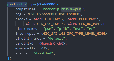
  2. Mastered the use of the RKNN toolchain

    • Installation and API of rknn-toolkit-lite2
    • Loading and inference of .rknn models
    • Specifying and configuring NPU cores
  3. Built a complete real-time detection pipeline

    • Camera capture -> NPU inference -> post-processing -> display
    • The FIFO + GStreamer display solution
    • Performance monitoring and FPS calculation
  4. Stumbled through various pitfalls

    • Dependency conflicts, camera initialization, display pipeline, etc.
    • Accumulated valuable debugging experience

8.2 Reflections

The RK3576's NPU is indeed powerful; 6 TOPS of compute is a top-tier configuration among edge devices. Although there are some pitfalls in using it (mainly dependency management), the overall experience is still good.

My biggest takeaway is: AI deployment is not easy! From model training to deployment, there is so much to consider - accuracy, speed, power, cost... every link requires trade-offs. But the moment I saw the real-time detection picture running smoothly, all the effort was worth it!

9. References

  1. RKNN-Toolkit2 Official Documentation
  2. RK3576 NPU Technical White Paper
  3. YOLOv5 Official Repository
  4. GStreamer Pipeline Design Guide
  5. My earlier articles

Appendix A: Complete YOLOv5 Inference Script

Due to length, the complete Python code has been integrated into the yolo_npu_display.sh script.

Key function descriptions:

  • xywh2xyxy(): bounding-box coordinate conversion
  • process(): YOLO output parsing
  • filter_boxes(): confidence filtering
  • nms_boxes(): non-maximum suppression (removes overlapping boxes)
  • yolov5_post_process(): complete post-processing flow

DshanPI-A1 Review Part 4: Modifying an Open-Source Gesture Project

· 7 min read
Yuxuan
100askTeam yuxuan.

All of the project modifications in this article are based mainly on compatibility, smoothness, screen display method, and camera invocation.

Display Output Adaptation

Main Adaptation Issues

1. RK3576 Runs a Pure Wayland Environment

RK3576 runs a pure Wayland environment with no X11 or libGL support, so the traditional cv2.imshow() cannot be used to display images.

[Solution]

Adopt the FIFO + GStreamer + Wayland display pipeline:

# Python side code
fifo = open('/tmp/gesture_fifo', 'wb')
while True:
_, jpeg = cv2.imencode('.jpg', processed_frame,
[cv2.IMWRITE_JPEG_QUALITY, 85])
fifo.write(jpeg.tobytes())
fifo.flush()
# Shell side code
# GStreamer reads the JPEG stream from the pipe and displays it
gst-launch-1.0 filesrc location=/tmp/gesture_fifo ! \
jpegparse ! jpegdec ! videoconvert ! waylandsink fullscreen=true

2. IMX415 Camera Color Anomaly on Second Launch

The IMX415 camera shows a color anomaly on its second launch, with the kernel reporting the error "no first iq setting".

[Solution]

Restart rkaiq_3A_server before each camera open:

def restart_3a(self):
os.system("killall rkaiq_3A_server 2>/dev/null")
time.sleep(2)
os.system("rm -f /tmp/.rkaiq_3A* 2>/dev/null")
os.system("/etc/init.d/S40rkaiq_3A start >/dev/null 2>&1")
time.sleep(5)

Project 1: Snake Game

Open-source project address: Project2/SnakeGame/main.py at main · WLHSDXN/Project2

Modification Process

1. Multi-Layer Detector Architecture

To accommodate different dependency environments, a three-layer detector fallback mechanism was designed:

Priority 1: cvzone (MediaPipe wrapper, high accuracy)
↓ unavailable
Priority 2: native MediaPipe (21 keypoints)
↓ unavailable
Priority 3: HSV skin-color detection (lightweight fallback)

Code implementation:

# Detector selection logic
if USE_CVZONE:
detector = CvzoneHandDetector(detectionCon=0.8, maxHands=1)
elif USE_MEDIAPIPE:
detector = MediapipeHandDetector(maxHands=1,
detectionCon=0.5,
drawLandmarks=False)
else:
detector = SimpleHandDetector() # HSV fallback solution

2. MediaPipe Integration and Wrapping

Implemented the MediapipeHandDetector class, returning a data format compatible with cvzone:

class MediapipeHandDetector:
def findHands(self, frame, flipType=False):
img_rgb = cv2.cvtColor(frame, cv2.COLOR_BGR2RGB)
results = self.hands.process(img_rgb)

hands = []
if results.multi_hand_landmarks:
for hand_landmarks in results.multi_hand_landmarks:
# Extract 21 keypoint coordinates
lmList = []
for lm in hand_landmarks.landmark:
x_px = int(lm.x * width)
y_px = int(lm.y * height)
lmList.append([x_px, y_px, lm.z])

hands.append({'lmList': lmList})

return hands, frame

[Key Point]

The index fingertip is lmList[8], used directly as the snake-head control point.

3. HSV Skin-Color Detection Fallback

When MediaPipe is unavailable, use simple skin-color detection:

def detect_hand_simple(frame):
hsv = cv2.cvtColor(frame, cv2.COLOR_BGR2HSV)
mask = cv2.inRange(hsv, [0, 30, 60], [255, 255, 255])

# Morphological denoising
kernel = np.ones((7, 7), np.uint8)
mask = cv2.morphologyEx(mask, cv2.MORPH_CLOSE, kernel, iterations=3)
mask = cv2.morphologyEx(mask, cv2.MORPH_OPEN, kernel, iterations=2)

contours, _ = cv2.findContours(mask, cv2.RETR_EXTERNAL,
cv2.CHAIN_APPROX_SIMPLE)
if contours:
c = max(contours, key=cv2.contourArea)
hull = cv2.convexHull(c)
# Extract the topmost point as the "fingertip"
topmost = hull[hull[:, :, 1].argmin()][0]
return topmost

4. MediaPipe Performance Tuning

Optimization 1: Use a Lightweight Model
self.hands = mp.solutions.hands.Hands(
model_complexity=0, # 0=lite, 1=full (default)
max_num_hands=1,
min_detection_confidence=0.5, # lower threshold for speed
min_tracking_confidence=0.5
)
Optimization 2: Disable Visualization Drawing
# Remove the time-consuming keypoint drawing
# mp_drawing.draw_landmarks(frame, landmarks, connections) # commented out
drawLandmarks=False # new switch
Optimization 3: Reduce Input Resolution
# 640x480 is already the optimal balance point
# Lowering further to 320x240 can boost FPS, but hurts detection accuracy
cap.set(cv2.CAP_PROP_FRAME_WIDTH, 640)
cap.set(cv2.CAP_PROP_FRAME_HEIGHT, 480)
Optimization 4: Optimize the Camera Buffer
cap.set(cv2.CAP_PROP_BUFFERSIZE, 1)  # reduce latency

[Optimization Effect]

FPS increased from 5-10 to 15-25 FPS, meeting the needs of game interaction.

5. File-Based Control Interface

Because keyboard input cannot be captured directly in FIFO mode, a control-file approach is used:

# Shell script section
# Read keypresses and write control files
stty echo icanon
while read n1 t 0.1 key; do
if [ "$key" = "r" ]; then
touch /tmp/snake_restart
elif [ "$key" = "q" ]; then
touch /tmp/snake_quit
fi
done
# Python section
# Detect control files
if os.path.exists('/tmp/snake_quit'):
print('Quit command detected')
break

if os.path.exists('/tmp/snake_restart'):
os.remove('/tmp/snake_restart')
# Reset game state
self.game.gameOver = False
self.game.points = []
self.game.previousHead = (0, 0)

Effect Demonstration

The code and demo video are in the attachments.

img

img

Project 2: Virtual Drawing Board

Open-source project: [Based on hand keypoint detection, air-control the mouse / air-draw] https://www.bilibili.com/video/BV1364y1h7PS?vd_source=a16ca768198c38baa684546cf5060811

Modification Process

1. Core Logic Extraction

Gesture Recognition Logic:
fingers = detector.fingersUp()  # returns 5 values, 1 means finger extended

# Mode 1: select tool (index + middle finger extended)
if fingers[1] and fingers[2]:
if y1 < 153: # in the top toolbar area
if 0 < x1 < 320: color = [50, 128, 250] # blue
elif 320 < x1 < 640: color = [0, 0, 255] # red
elif 640 < x1 < 960: color = [0, 255, 0] # green
elif 960 < x1 < 1280: color = [0, 0, 0] # eraser

# Mode 2: draw (only index finger extended)
elif fingers[1] and not fingers[2]:
cv2.line(imgCanvas, (xp, yp), (x1, y1), color, brushThickness)
Canvas Compositing Logic:
# 1. Convert the canvas to grayscale and binarize it
imgGray = cv2.cvtColor(imgCanvas, cv2.COLOR_BGR2GRAY)
_, imgInv = cv2.threshold(imgGray, 50, 255, cv2.THRESH_BINARY_INV)

# 2. Composite with bitwise operations
img = cv2.bitwise_and(img, imgInv) # keep non-drawing area of camera frame
img = cv2.bitwise_or(img, imgCanvas) # overlay drawing content

2. Display System Rebuild

Reuse the snake game's display solution: FIFO + GStreamer.

3. Toolbar Internalization

The original project depended on 4 PNG images as the toolbar, which is inconvenient for managing external resources on an embedded system.

[Solution]

Generate the toolbar with OpenCV drawing APIs:

def create_header(self):
"""Dynamically generate the toolbar"""
header = np.zeros((100, self.width, 3), np.uint8)
header[:] = (200, 200, 200) # gray background

tools = [
((250, 128, 50), "Blue"), # BGR format
((0, 0, 255), "Red"),
((0, 255, 0), "Green"),
((0, 0, 0), "Eraser")
]

section_width = self.width // 4
for i, (color, label) in enumerate(tools):
x1 = i * section_width
x2 = (i + 1) * section_width

# Draw color block
cv2.rectangle(header, (x1 + 10, 20), (x2 - 10, 80), color, -1)
cv2.rectangle(header, (x1 + 10, 20), (x2 - 10, 80),
(255, 255, 255), 2) # white border

# Text label
cv2.putText(header, label, (x1 + 20, 95),
cv2.FONT_HERSHEY_SIMPLEX, 0.5, (50, 50, 50), 1)

return header

This way there is zero dependency on external resources, which is better for porting and project development!

4. Camera and 3A Service Adaptation

Reuse the snake game's fix.

5. Resolution vs. Performance Trade-off

[Original Configuration]:

width = 1280, height = 720
canvas: imgCanvas = np.zeros((720, 1280, 3), np.uint8)

[RK3576 Optimization]

width = 640, height = 480  # reduce resolution by 50%
canvas: imgCanvas = np.zeros((480, 640, 3), np.uint8)

[Reasons]

  1. MediaPipe's FPS roughly doubles at 640x480
  2. The drawing-board application does not demand as high a resolution as vision recognition
  3. JPEG encoding/transmission is faster

[Toolbar Adaptation]

Original: 153 pixels tall at the top, divided into 4 regions 320 pixels wide RK3576: 100 pixels tall at the top, divided into 4 regions 160 pixels wide

section_width = self.width // 4  # adaptive width
if y1 < 100: # toolbar height
if 0 < x1 < section_width:
self.color = (250, 128, 50) # blue
elif section_width < x1 < section_width * 2:
self.color = (0, 0, 255) # red
# ...

6. Interaction Control Improvements

1. Clear-Canvas Mechanism

[Original]

if all(x >= 1 for x in fingers):
imgCanvas = np.zeros((720, 1280, 3), np.uint8)

[Problem]

High false-trigger rate; inconvenient for fine control.

[RK3576 Improvement]

Use keypress control:

# Shell side
while read -n1 -t 0.1 key; do
if [ "$key" = "c" ]; then
touch /tmp/painter_clear
fi
done
# Python side
if os.path.exists('/tmp/painter_clear'):
os.remove('/tmp/painter_clear')
self.imgCanvas = np.zeros((self.height, self.width, 3), np.uint8)
print("Canvas cleared")
2. Exit Control

[Original]

Can only capture the keyboard through cv2.waitKey(1), dependent on window focus.

[RK3576]

Dual exit mechanism:

  1. Keypress control: touch /tmp/painter_quit -> Python detects it and exits

  2. Ctrl+C: Shell script traps the signal -> kills all processes -> cleans up the FIFO

Effect Demonstration

The code and demo video are in the attachments.

img

img

Technical Summary and Lessons

  1. Cross-Platform Display Adaptation PC GUI solutions do not apply to embedded systems; the output method must be chosen based on system characteristics (Wayland/Framebuffer).

  2. Resource Internalization Embedded systems tend toward single-file deployment; external resources should be turned into code-generated content or packed into the program.

  3. Tiered Performance Optimization

    • Algorithm layer: lightweight models
    • Implementation layer: disable non-essential drawing
    • Hardware layer: buffer/resolution tuning
  4. Interaction Adaptation Keyboard/mouse events that GUIs depend on must be converted to file control or GPIO triggers.

DshanPI-A1 Review Part 3: OpenCV Debugging and CPU-Based Gesture Recognition Inference

· 10 min read
Yuxuan
100askTeam yuxuan.

Previously we finished debugging the camera and the screen, so now we can finally start working on gesture recognition!

This time I will implement a real-time, OpenCV-based gesture recognition system on the RK3576 Buildroot system. The system can recognize five gestures (fist/one finger, two, three, four, five fingers) and display the processing results on the screen in real time.

Given the particularities of embedded systems, we will focus on how to render images in a Wayland environment with no X11 and no OpenGL.

Gesture Recognition Algorithm

Principle

Because there are concavities between our spread fingers, we can accurately identify the number of fingers by calculating the angle and depth of these concavity points.

1. Skin Color Detection

Use the HSV color space to extract the skin-color region:

def detect_hand(self, frame):
hsv = cv2.cvtColor(frame, cv2.COLOR_BGR2HSV)
mask = cv2.inRange(hsv, [0, 30, 60], [25, 255, 255]) # skin color range

# Morphological processing for denoising
kernel = np.ones((7, 7), np.uint8)
mask = cv2.morphologyEx(mask, cv2.MORPH_CLOSE, kernel, iterations=3)
mask = cv2.morphologyEx(mask, cv2.MORPH_OPEN, kernel, iterations=2)

# Find the largest contour
contours, _ = cv2.findContours(mask, cv2.RETR_EXTERNAL, cv2.CHAIN_APPROX_SIMPLE)
if contours:
c = max(contours, key=cv2.contourArea)
if cv2.contourArea(c) > 3000: # area threshold to filter noise
return c, mask
return None, mask

2. Finger Counting (Convex Hull Defect Method)

Identify fingers by detecting the concavity points of the hand contour:

def recognize(self, contour):
hull = cv2.convexHull(contour, returnPoints=False)
defects = cv2.convexityDefects(contour, hull)

finger_count = 0
for i in range(defects.shape[0]):
s, e, f, d = defects[i, 0]
start = tuple(contour[s][0]) # convex point 1
end = tuple(contour[e][0]) # convex point 2
far = tuple(contour[f][0]) # concavity point (between fingers)

# Calculate the angle to determine whether it is a valid fingertip
a = np.linalg.norm(np.array(start) - np.array(end))
b = np.linalg.norm(np.array(start) - np.array(far))
c = np.linalg.norm(np.array(end) - np.array(far))
angle = np.arccos((b**2 + c**2 - a**2) / (2 * b * c))
if angle <= np.pi / 2.2 and d > 8000: # angle and depth thresholds
finger_count += 1

gestures = ["Fist/One", "Two", "Three", "Four", "Five"]
return gestures[finger_count]

How to Display the OpenCV-Processed Image

Theory alone is not enough - we need practice! How to display the OpenCV-processed image is the focus of this tutorial. Normally we use cv2.imshow() to display an image, but on an embedded system without X11/OpenGL this method is unavailable. We need to use the GStreamer + Wayland solution (the same approach as in our previous article).
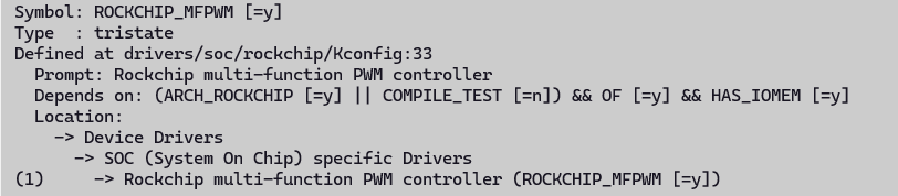
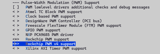
Exploration of Solutions

Solution A: stdin Pipe Transmission

The most intuitive idea is to transmit image data through the stdin pipe:
proc = subprocess.Popen(['gst-launch-1.0', 'fdsrc', '!', ...], stdin=subprocess.PIPE)
proc.stdin.write(frame_data)

Result: Broken pipe errors occurred frequently and the data transmission was unstable. I suspect the pipe was timing out and closing automatically, or my format was wrong. So I directly tried using a FIFO to transmit raw data.

Solution B: Named Pipe (FIFO) for Raw Data Transmission

Try to transmit raw RGB data through a FIFO:

mkfifo /tmp/video_fifo

img

Unfortunately, this caused kernel crashes all too easily. At this point I was facing several problems: if I only used the command line to view the recognition results, I had no way of knowing whether the camera was running normally; but OpenCV and GStreamer reading the camera simultaneously was not possible (the camera can only be read by one process). Later I realized that the GStreamer display did not need to read the camera frame in real time - I only needed to display what OpenCV had processed. So I got to work, and tried to pass the OpenCV-processed image directly to the screen through GStreamer, but my skills were not up to the task and it came to nothing: the pipe either errored or closed. I stopped to think slowly, and finally came up with Solution C (getting to this step had already taken three days).
Solution C: Multi-File Sequence

Change the approach: save the processed images as a sequence of JPEG files:

# Python side
cv2.imwrite(f'/dev/shm/gesture_frames/frame_{frame_index:03d}.jpg', processed)
# GStreamer side
gst-launch-1.0 multifilesrc location=frame_%03d.jpg loop=true ! jpegdec ! ...

Result: The screen finally showed some movement - I was thrilled! But the effect was poor, with severe ghosting, and because it was reading the folder's images in a loop, it kept looping the playback, which hurt both the appearance and the experience. So I decided to leverage the FIFO and, building on the previous idea, upgrade it to the current solution:

OpenCV finishes processing a frame -> immediately encodes it as JPEG -> writes directly into the FIFO -> GStreamer immediately decodes and displays it

Solution D: FIFO + JPEG Stream (Final Solution!)

# Python side: write JPEG data directly into the FIFO
fifo = open('/tmp/gesture_fifo', 'wb')
_, jpeg = cv2.imencode('.jpg', processed, [cv2.IMWRITE_JPEG_QUALITY, 85])
fifo.write(jpeg.tobytes())
fifo.flush()
# GStreamer side: use jpegparse to automatically split JPEG frames
gst-launch-1.0 filesrc location=/tmp/gesture_fifo ! jpegparse ! jpegdec ! ...

Supplement: Why does the JPEG stream work?

  1. The JPEG format has built-in start (0xFFD8) and end (0xFFD9) markers
  2. GStreamer's jpegparse plugin can automatically recognize boundaries and split independent JPEG frames
  3. It avoids the packet-sticking problem of raw data streams

Result: At last I could observe the picture smoothly (the pipeline did not stutter - it was even smoother than directly opening the camera icon on the screen to view the camera feed). I will put the demo video and code in the attachments.

img img

Bonus - The Camera's Second Launch Was Greenish and Dark

Problem Description

I used the IMX415 camera on the RK3576 Buildroot system and displayed the picture through GStreamer + Wayland. I ran into a bizarre issue: the first time the camera was started the colors were normal, but after the second start the picture became dark and greenish.

img

Preliminary Analysis: Comparing the Boot Logs

First I compared the kernel logs of the two launches and found a key difference:

First launch (normal colors):

[20.528641] rkisp_hw 27c00000.isp: set isp clk = 594000000Hz
[20.529097] rkcif-mipi-lvds 3: stream[0] start streaming
[20.529317] rockchip-csi2-dphy 3: dphy3, data_rate_mbps 892
[20.529356] imx415 3-0037: s_stream: 1.3864x2192, hdr: 0, bpp: 10

Second launch (abnormal colors):

[79.209321] rkisp_hw 27c00000.isp: set isp clk = 594000000Hz
[79.209967] rkisp rkisp-vir3: first params buf queue
[79.210051] rkisp rkisp-vir3: id: 0 no first iq setting cfg_upd: c000dfecc7fe473b en_upd: 0 en s: 5ffcc7fe473b
[79.210351] rkcif-mipi-lvds 3: stream[0] start streaming

Key finding: the second launch had one extra warning no first iq setting. This indicates that the ISP's image quality parameters were not loaded correctly, causing wrong default parameters to be used, which made the colors dark and greenish.

Problem-Solving Process

Phase 1: Attempting a Hardware-level Fix

At first I thought the ISP driver state had not been reset correctly, and tried several methods:

  1. Attempt to unbind/bind the ISP driver:

    echo "27c00000.isp" > /sys/bus/platform/drivers/rkisp_hw/unbind
    echo "27c00000.isp" > /sys/bus/platform/drivers/rkisp_hw/bind

    Result: the camera could not be opened at all - the operation was too aggressive and completely messed up the driver state.

  2. Tried v4l2-ctl reset, media-ctl reset, etc., but none of them solved the problem.

Phase 2: In-Depth Diagnosis of the System Configuration

I began systematically diagnosing the entire camera subsystem:

# Find the IQ parameter file
find / -name "*imx415*.xml" -o -name "*imx415*.json" 2>/dev/null
# Result: found /etc/iqfiles/imx415_CMK-OT2022-PX1_IR0147-50IRC-8M-F20.json

# Check the 3A server
ps aux | grep rkaiq_3A_server
# Result: the server is running

# View device topology
v4l2-ctl --list-devices
# Confirm /dev/video-camera0 -> video11

Key findings:

  • The IQ parameter file exists
  • The 3A server (rkaiq_3A_server) is running
  • But why were the IQ parameters not loaded?

Phase 3: Capturing the 3A Server Log

I decided to run the 3A server in the foreground to view detailed output:

killall rkaiq_3A_server
/usr/bin/rkaiq_3A_server 2>&1 &

The startup log showed:

DBG: get rkisp-isp-subdev devname: /dev/v4l-subdev3
DBG: get rkisp-input-params devname: /dev/video18
DBG: get rkisp-statistics devname: /dev/video17
XCORE: K: cid[1] rk_aiq_uapi2_sysctl_init success. iq: /etc/iqfiles//imx415_CMK-OT2022-PX1_IR0147-50IRC-8M-F20.json
XCORE: K: cid[1] rk_aiq_uapi2_sysctl_prepare success. mode: 0
DBG: /dev/media1: wait stream start event..

Major finding: the 3A server was actually working fine! The IQ file had been loaded successfully!

At this point I ran a second camera launch test and observed:

[625.216117] rkisp-vir3: waiting on params stream one event timeout

The truth came out: on the second launch, the 3A server timed out and did not respond!

Phase 4: Finding the Root Cause

Through multiple tests and log analysis, I finally understood the nature of the problem:

First launch flow (normal):

  1. When the system boots, the 3A server starts automatically
  2. The 3A server loads the IQ parameter file into memory
  3. The 3A server pre-prepares the IQ parameter buffer
  4. GStreamer starts the camera
  5. The ISP requests IQ parameters
  6. The 3A server responds immediately and pushes the IQ parameters
  7. Colors are normal

Second launch flow (abnormal):

  1. Stop the first GStreamer process
  2. The 3A server is still running, but has entered some waiting state
  3. The IQ parameter buffer has already been consumed
  4. GStreamer is restarted immediately
  5. The ISP requests IQ parameters
  6. The 3A server cannot respond in time or is in an abnormal state
  7. The ISP uses default parameters to process the first frame
  8. The no first iq setting warning appears
  9. Colors are dark and greenish

Solution

The root cause of the problem is: after the camera's first run, the 3A server enters an abnormal state and cannot correctly respond to the IQ parameter request of the second launch.

The final fix is simple: restart the 3A server before each camera launch.

I wrote a wrapper script:

#!/bin/sh

echo "=== Starting Camera with 3A Server Reset ==="

# 1. Stop all camera processes
pkill -9 gst-launch 2>/dev/null

# 2. Restart the 3A server
killall rkaiq_3A_server 2>/dev/null
sleep 2
rm -f /tmp/.rkaiq_3A*

# 3. Start the 3A server
/etc/init.d/S40rkaiq_3A start
echo "Waiting for 3A server to initialize..."
sleep 5

# 4. Confirm the 3A server is running normally
if ! pgrep rkaiq_3A_server > /dev/null; then
echo "ERROR: 3A server failed to start!"
exit 1
fi

echo "3A server ready, starting camera..."

# 5. Start the camera
gst-launch-1.0 v4l2src device=/dev/video11 ! \
video/x-raw,format=NV12,width=640,height=480,framerate=30/1 ! \
waylandsink

echo "Camera stopped"
exit 0

img

Verification Result

img

After using the new script, I started the camera several times in a row and the colors were always normal; the log no longer showed no first iq setting or timeout errors.

Lessons Learned

  1. Comparing logs is key to discovering problems: by comparing the logs of the normal and abnormal cases, I quickly located the key clue no first iq setting

  2. Diagnose systematically: do not blindly try things; first check the state of each component (IQ file, 3A server, device node)

  3. Run in the foreground to see detailed logs: many background-service problems require foreground execution to see detailed output

  4. Understand the cooperation between components: the RK platform's camera involves cooperation among the ISP driver, the 3A server, and the IQ parameter file - a problem in any link will cause an anomaly

  5. State management matters: embedded-system service-restart problems are often caused by improper state-machine management; a thorough reset is the most reliable solution.

DshanPI-A1 Review Part 2: Gesture Recognition Programming Environment Setup and Screen Debugging

· 6 min read
Yuxuan
100askTeam yuxuan.

In this review, I will install the necessary tools for the gesture recognition system and debug the screen.

Hardware and Environment Preparation

Before starting, let's clarify the equipment and environment on hand:

  • Core board: Dshanpi-A1, with the Rockchip RK3576 chip as the main SoC.

  • Screen: A 480x800 resolution MIPI screen.

  • System: Buildroot Linux system.

  • Official SDK

Install Development Tools

Here is the list for this time:

Package/Configuration CategoryRecommended Options and Purpose
Python Environmentpython3: Core interpreter. python-pip: Used to install Python packages not included in Buildroot. python-numpy: Provides efficient numerical computation support for OpenCV and other libraries. python-setuptools: A base build dependency for some Python packages.
Computer Vision and Image Processingopencv4: Be sure to enable python3 support. Provides the core computer vision library for image processing and gesture recognition algorithms. opencv4 contrib modules: Includes additional, more advanced algorithms.
Camera and Display Supportgstreamer1 and related plugins: Build pipelines for camera image capture and screen display. gst1-plugins-base, gst1-plugins-good, gst1-plugins-bad, gst1-plugins-ugly: Provide a rich set of codecs and functional elements. gst1-python: Allows creating and manipulating GStreamer pipelines in Python.

SDK Configuration Process

1. Select the Chip Type

./build.sh chip

img

img

2. Enter buildroot Configuration

cd buildroot
make menuconfig

img

3. Select Target packages

img

4. Install the Python Environment

When you cannot find the installation path, press the / key to search:

img

Enter python3 to search:

img

Enter the displayed Location path to configure:

img

img

5. Save the Configuration and Build

make

Return to the SDK main directory and run:

./build.sh rootfs
./build.sh updateimg

Finally, flash and run it on the development board.

Development Board Debugging

Check Tool Installation

python3 --version
pip3 --version
python3 -c "import numpy; print('NumPy version:', numpy.__version__)"
python3 -c "import cv2; print('OpenCV version:', cv2.__version__)"

img

Screen Debugging

Problem Analysis

The system is already running the Weston compositor, which means we have a graphical interface environment. Attempting to directly operate the FrameBuffer (/dev/fb0) is ineffective because Weston has already occupied the display interface.

Through system inspection, we found:

  • The /dev/fb0 device exists
  • The screen status is connected
  • The resolution is 480x800

img

Solution: GStreamer + Wayland

GStreamer Basic Test

gst-launch-1.0 videotestsrc pattern=smpte ! video/x-raw,width=480,height=800 ! waylandsink sync=false

img

Camera Direct-to-Display Test

gst-launch-1.0 v4l2src device=/dev/video11 ! video/x-raw,width=640,height=480 ! videoconvert ! waylandsink sync=false

img

Note: Please replace the device parameter with your camera's device node

Test Script

#!/usr/bin/env python3
# fixed_display_test.py

import subprocess
import time
import os

def check_camera_devices():
"""Check available camera devices"""
print("=== Camera Device Check ===")

try:
# Use v4l2-ctl to check devices
result = subprocess.run(["v4l2-ctl", "--list-devices"],
capture_output=True, text=True)
if result.returncode == 0:
print("Found video devices:")n print(result.stdout)
else:
print("v4l2-ctl command execution failed")
except Exception as e:
print(f"Failed to check camera devices: {e}")

# Test common camera devices
camera_devices = ["/dev/video11", "/dev/video0", "/dev/video1", "/dev/video2"]
print("\nTesting camera devices:")

for device in camera_devices:
if os.path.exists(device):
print(f"Testing device: {device}")
try:
# Try to test the camera using GStreamer
cmd = [
"gst-launch-1.0",
"-v",
"v4l2src", f"device={device}", "!",
"video/x-raw,width=640,height=480,framerate=15/1", "!",
"videoconvert", "!",
"waylandsink", "sync=false"
]

process = subprocess.Popen(cmd)
time.sleep(3) # Display for 3 seconds
process.terminate()
process.wait()
print(f" {device}: Camera working normally")
return device

except Exception as e:
print(f"{device}: Test failed - {e}")
else:
print(f"{device}: Device does not exist")

return None

def test_static_patterns():
"""Test static patterns (will not change)"""
print("\n=== Static Pattern Test ===")

# Set Wayland environment
os.environ['WAYLAND_DISPLAY'] = 'wayland-0'

# Test static patterns (will not change)
static_patterns = [
("smpte100", "SMPTE 100% color bars"),
("ball", "Clock pattern"),
("blink", "Blink pattern"),
("pinwheel", "Pinwheel pattern"),
("spokes", "Spokes pattern"),
]

for pattern, description in static_patterns:
print(f"Displaying: {description}")
try:
cmd = [
"gst-launch-1.0",
"videotestsrc", f"pattern={pattern}", "!",
"video/x-raw,width=480,height=800,framerate=15/1", "!",
"waylandsink", "sync=false"
]

process = subprocess.Popen(cmd)
time.sleep(3)
process.terminate()
process.wait()
print(f"{description} displayed successfully")

except Exception as e:
print(f"{description} display failed: {e}")

def test_custom_resolution():
"""Test custom resolution display"""
print("\n=== Custom Resolution Test ===")

resolutions = [
(480, 800, "Portrait 480x800"),
(800, 480, "Landscape 800x480"),
(640, 480, "Standard 640x480"),
(400, 800, "Portrait 400x800"),
]

for width, height, desc in resolutions:
print(f"Testing resolution: {desc}")
try:
cmd = [
"gst-launch-1.0",
"videotestsrc", "pattern=smpte100", "!",
f"video/x-raw,width={width},height={height},framerate=15/1", "!",
"videoconvert", "!",
"waylandsink", "sync=false"
]

process = subprocess.Popen(cmd)
time.sleep(2)
process.terminate()
process.wait()
print(f" {desc} displayed successfully")

except Exception as e:
print(f" {desc} display failed: {e}")

if __name__ == "__main__":
print("=" * 50)

# 1. Check camera
camera_device = check_camera_devices()

# 2. Test static patterns
test_static_patterns()

# 3. Test different resolutions
test_custom_resolution()

print("\n" + "=" * 50)
if camera_device:
print(f"Available camera device: {camera_device}")
else:
print("No available camera device found")
print("All tests completed")

img

img

Run Results

image-20251222165424798

image-20251222165428939

I will put the demo video in the attachments

Bonus Chapter: FileZilla File Transfer

FileZilla Connection Settings

FileZilla - The free FTP solution

Check SSH Service

ss -tuln | grep 22

img

Network Sharing Settings

img

img

img

Select the network that can access the internet, and click Properties:

img

image-20251222165505322

Connect to the Development Board

ifconfig

img

Connect using FileZilla:

  • IP: Development board IP address
  • Username: root
  • Password: rockchip
  • Port: 22

Summary

Looking back at the entire debugging process, the following key points are worth special attention:

  1. Display Path Selection: On systems running a compositor such as Weston, prioritize the GStreamer + waylandsink solution for displaying images, rather than directly operating the FrameBuffer.

  2. Camera Device Node: Be sure to use the v4l2-ctl --list-devices command to confirm the device node corresponding to the camera, and specify it correctly in the code.

  3. Screen Resolution: Note that the screen resolution detected by the system (which can be queried via cat /sys/class/drm/card0-DSI-1/modes) may be slightly different from the physical resolution. When creating display frames, use this as the reference or make adjustments accordingly.

At this point, we have successfully set up the gesture recognition programming environment on the Dshanpi A1 development board and resolved the display issues with the MIPI screen and camera. Although the process was full of twists and turns, it laid a solid foundation for the subsequent actual writing of gesture recognition algorithms. I hope my experience can be of help to everyone!